Everything you need to boot this motherboard is included in this Easy Installation Guide. For more information, a complete Online User's Manual can be found in the Bonus Pack CD Disc. Thanks for the help of saving our earth.
1. JP14 Clear CMOS
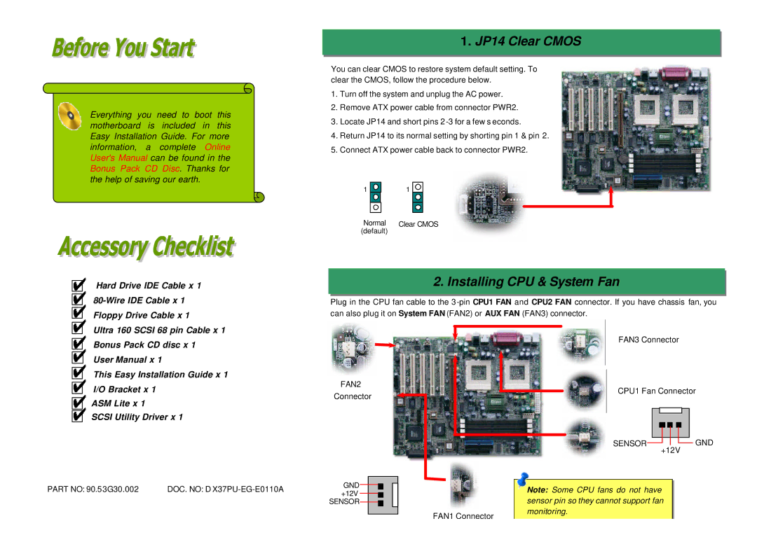
You can clear CMOS to restore system default setting. To clear the CMOS, follow the procedure below.
1.Turn off the system and unplug the AC power.
2.Remove ATX power cable from connector PWR2.
3.Locate JP14 and short pins 2
4.Return JP14 to its normal setting by shorting pin 1 & pin 2.
5.Connect ATX power cable back to connector PWR2.
1 | 1 |
Normal | Clear CMOS |
(default) |
|
Hard Drive IDE Cable x 1
2. Installing CPU & System Fan
Plug in the CPU fan cable to the
Ultra 160 SCSI 68 pin Cable x 1
Bonus Pack CD disc x 1
User Manual x 1
This Easy Installation Guide x 1
I/O Bracket x 1
ASM Lite x 1
SCSI Utility Driver x 1
PART NO: 90.53G30.002 | DOC. NO: D |
FAN2
Connector
GND![]()
![]() +12V
+12V ![]()
![]()
SENSOR![]()
![]()
![]()
FAN1 Connector
FAN3 Connector
CPU1 Fan Connector
SENSOR![]()
![]()
![]() GND +12V
GND +12V
Note: Some CPU fans do not have sensor pin so they cannot support fan monitoring.