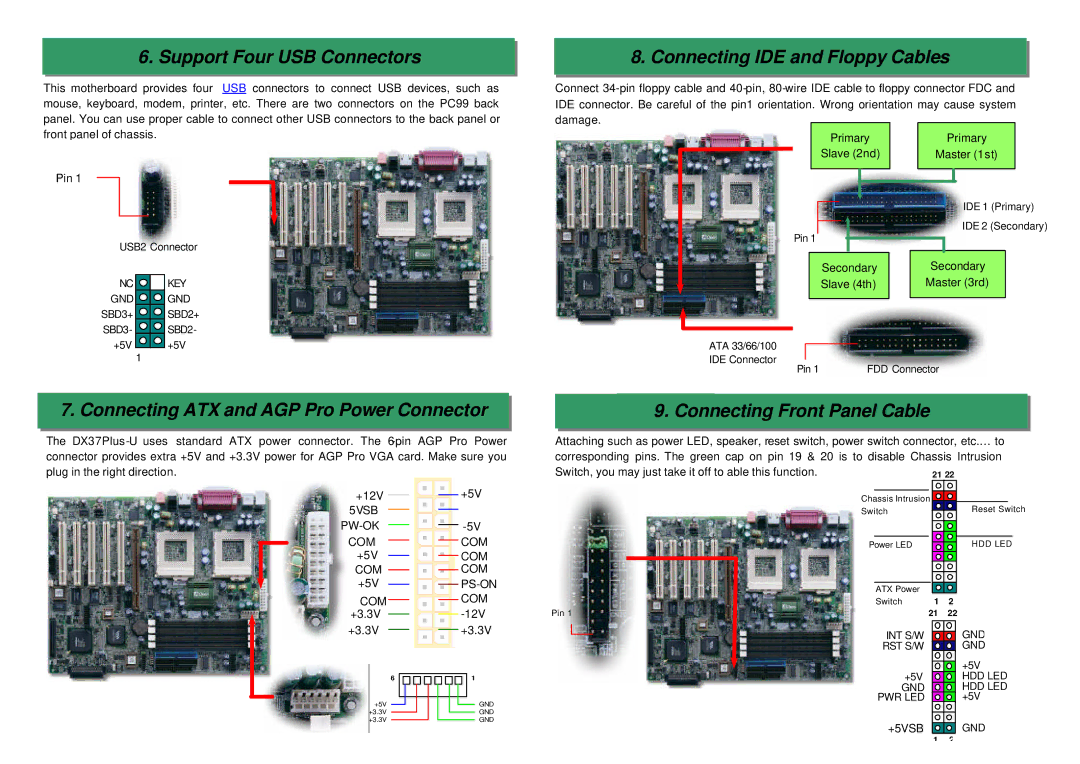
6. Support Four USB Connectors
This motherboard provides four USB connectors to connect USB devices, such as mouse, keyboard, modem, printer, etc. There are two connectors on the PC99 back panel. You can use proper cable to connect other USB connectors to the back panel or front panel of chassis.
Pin 1
USB2 Connector
NC ![]() KEY
KEY
GND ![]()
![]() GND
GND
SBD3+ ![]()
![]() SBD2+
SBD2+
SBD3- ![]()
![]() SBD2-
SBD2-
+5V ![]() +5V
+5V
1
7. Connecting ATX and AGP Pro Power Connector
The DX37Plus
8. Connecting IDE and Floppy Cables
Connect
Primary | Primary | ||
Slave (2nd) | Master (1st) | ||
|
|
|
|
|
|
|
|
IDE 1 (Primary)
IDE 2 (Secondary)
Pin 1
|
| Secondary |
Secondary |
| |
Slave (4th) |
| Master (3rd) |
|
|
|
ATA 33/66/100 |
|
IDE Connector | FDD Connector |
Pin 1 |
9. Connecting Front Panel Cable
Attaching such as power LED, speaker, reset switch, power switch connector, etc.… to
corresponding pins. The green cap on pin 19 & 20 is to disable Chassis Intrusion Switch, you may just take it off to able this function.
+12V
5VSB
COM +5V COM +5V
COM +3.3V
+5V
COM
COM
COM
PS-ON
COM
Chassis Intrusion |
Switch |
Power LED |
|
|
|
|
|
|
| ATX Power |
|
|
|
|
| Switch | 1 | 2 | ||
Pin 1 | 21 | 22 | |||
Reset Switch
HDD LED
+3.3V
6
+5V
+3.3V
+3.3V
+3.3V
1
GND
GND
GND
INT S/W ![]() GND
GND
RST S/W ![]() GND
GND
| +5V |
+5V | HDD LED |
GND | HDD LED |
PWR LED | +5V |
+5VSB | GND |
1 | 2 |