Front Panel Buttons and Display Interface
Use the three buttons on the front panel of the Back-UPS and the display interface to configure the Back-UPS.
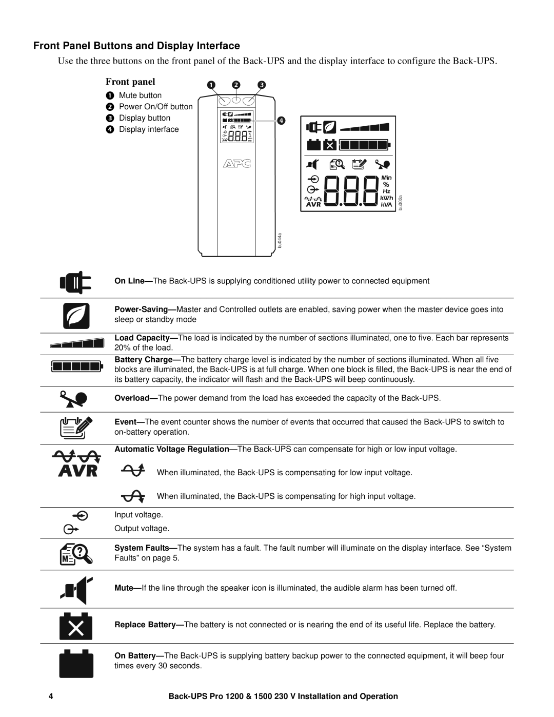
Front panel
Mute button
Power On/Off button
Display button Display interface
bu002a
bu044a
On Line—The Back-UPS is supplying conditioned utility power to connected equipment
Power-Saving—Master and Controlled outlets are enabled, saving power when the master device goes into sleep or standby mode
Load Capacity—The load is indicated by the number of sections illuminated, one to five. Each bar represents 20% of the load.
Battery Charge—The battery charge level is indicated by the number of sections illuminated. When all five blocks are illuminated, the Back-UPS is at full charge. When one block is filled, the Back-UPS is near the end of its battery capacity, the indicator will flash and the Back-UPS will beep continuously.
Overload—The power demand from the load has exceeded the capacity of the Back-UPS.
Event—The event counter shows the number of events that occurred that caused the Back-UPS to switch to on-battery operation.
Automatic Voltage Regulation—The Back-UPS can compensate for high or low input voltage.
When illuminated, the Back-UPS is compensating for low input voltage.
When illuminated, the Back-UPS is compensating for high input voltage.
Input voltage.
Output voltage.
System Faults—The system has a fault. The fault number will illuminate on the display interface. See “System Faults” on page 5.
Mute—If the line through the speaker icon is illuminated, the audible alarm has been turned off.
Replace Battery—The battery is not connected or is nearing the end of its useful life. Replace the battery.
On Battery—The Back-UPS is supplying battery backup power to the connected equipment, it will beep four times every 30 seconds.