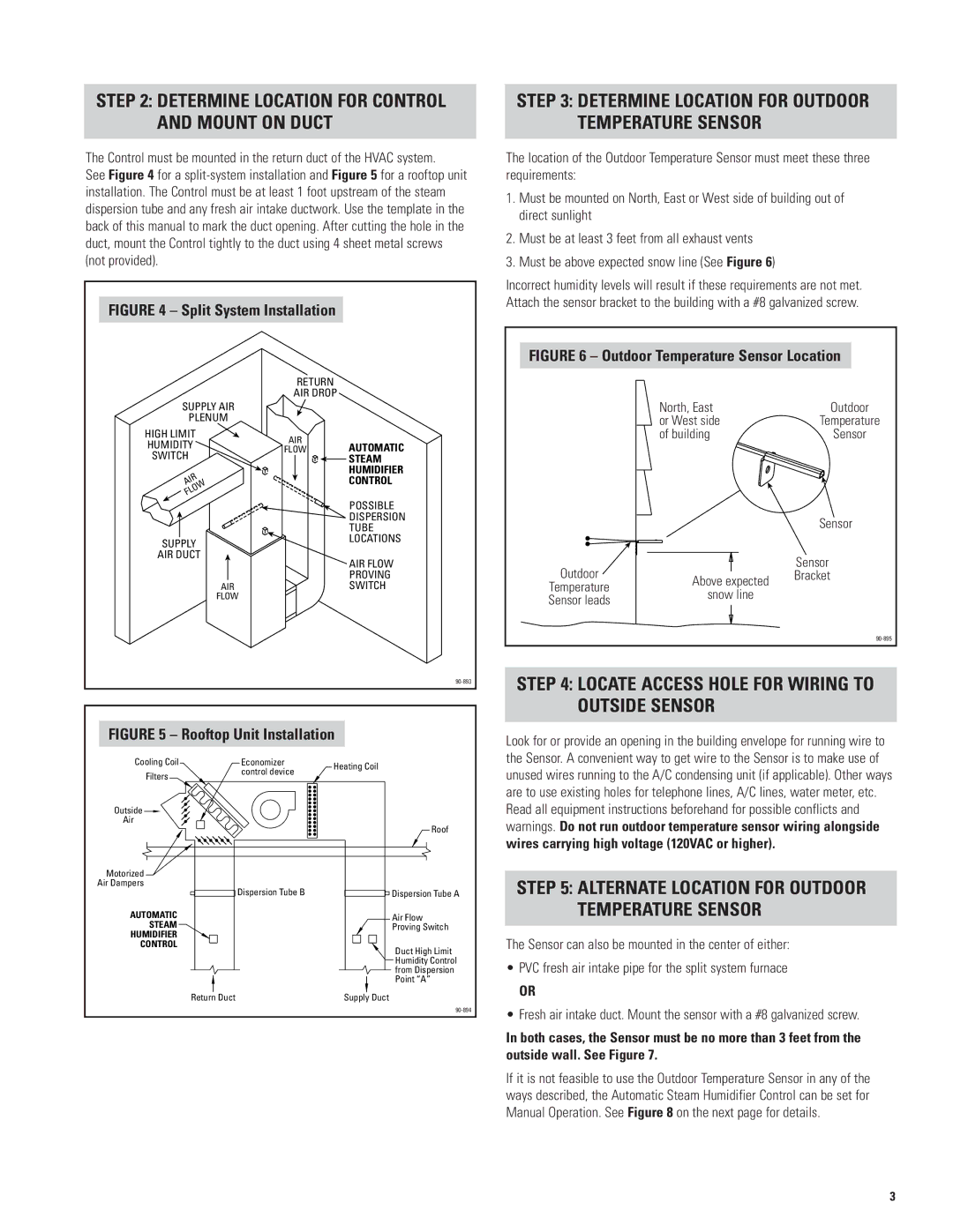
STEP 2: DETERMINE LOCATION FOR CONTROL AND MOUNT ON DUCT

The Control must be mounted in the return duct of the HVAC system.

See Figure 4 for a split-system installation and Figure 5 for a rooftop unit installation. The Control must be at least 1 foot upstream of the steam dispersion tube and any fresh air intake ductwork. Use the template in the back of this manual to mark the duct opening. After cutting the hole in the duct, mount the Control tightly to the duct using 4 sheet metal screws (not provided).

FIGURE 4 – Split System Installation


RETURN


AIR DROP


SUPPLY AIR


PLENUM


HIGH LIMIT

AIR


HUMIDITY

AUTOMATIC

FLOW

SWITCH


STEAM


HUMIDIFIER

AIR


CONTROL

FLOW


POSSIBLE


DISPERSION


TUBE

SUPPLY


LOCATIONS

AIR DUCT


AIR FLOW


PROVING

AIR


SWITCH

FLOW


90-893

FIGURE 5 – Rooftop Unit Installation

Cooling Coil

Economizer

Heating Coil

Filters

control device


Outside

Air

Roof

Motorized

Air Dampers


Dispersion Tube B


Dispersion Tube A

AUTOMATIC


Air Flow

STEAM


Proving Switch

HUMIDIFIER


CONTROL


Duct High Limit


Humidity Control


from Dispersion


Point “A”

Return


Duct

Supply


Duct


90-894

STEP 3: DETERMINE LOCATION FOR OUTDOOR TEMPERATURE SENSOR

The location of the Outdoor Temperature Sensor must meet these three requirements:

1.Must be mounted on North, East or West side of building out of direct sunlight

2.Must be at least 3 feet from all exhaust vents

3.Must be above expected snow line (See Figure 6)

Incorrect humidity levels will result if these requirements are not met. Attach the sensor bracket to the building with a #8 galvanized screw.

FIGURE 6 – Outdoor Temperature Sensor Location


North, East

Outdoor


or West side

Temperature


of building

Sensor


Sensor

Outdoor


Sensor

Above expected

Bracket

Temperature


snow line


Sensor leads


90-895

STEP 4: LOCATE ACCESS HOLE FOR WIRING TO OUTSIDE SENSOR

Look for or provide an opening in the building envelope for running wire to the Sensor. A convenient way to get wire to the Sensor is to make use of unused wires running to the A/C condensing unit (if applicable). Other ways are to use existing holes for telephone lines, A/C lines, water meter, etc. Read all equipment instructions beforehand for possible conflicts and warnings. Do not run outdoor temperature sensor wiring alongside

wires carrying high voltage (120VAC or higher).

STEP 5: ALTERNATE LOCATION FOR OUTDOOR TEMPERATURE SENSOR

The Sensor can also be mounted in the center of either:

PVC fresh air intake pipe for the split system furnace

OR

Fresh air intake duct. Mount the sensor with a #8 galvanized screw.

In both cases, the Sensor must be no more than 3 feet from the outside wall. See Figure 7.

If it is not feasible to use the Outdoor Temperature Sensor in any of the ways described, the Automatic Steam Humidifier Control can be set for Manual Operation. See Figure 8 on the next page for details.

3

Page 3
Image 3
Aprilaire 1150, 1160 Locate Access Hole for Wiring to Outside Sensor, Determine Location for Control and Mount on Duct

1180, 1150, 1160 specifications

Aprilaire 1160, 1150, and 1180 are three advanced whole-home humidifiers designed to enhance indoor air quality, maintain comfort levels, and promote a healthier living environment. These models are engineered to tackle the challenges of dry air, which can lead to various health issues such as dry skin, irritated sinuses, and increased allergens. Each model has unique features and technologies that cater to specific needs, making them suitable for a variety of households.

The Aprilaire 1160 is a high-capacity option capable of humidifying homes up to 3,600 square feet. One of its most notable features is the automatic humidistat, which continuously measures indoor humidity levels and adjusts the humidifier's operation accordingly. This ensures optimum comfort without unnecessary energy consumption. The 1160 also utilizes the evaporative technology, which draws in dry air and passes it through a moistened wick, allowing moisture to evaporate and be released into the home. Additionally, its self-regulating design prevents oversaturation and ensures consistent humidity levels year-round.

The Aprilaire 1150, designed for homes up to 3,000 square feet, offers similar benefits, spotlighting simplicity and efficiency. It features an easy-to-use manual humidistat that lets homeowners set their desired humidity levels. The 1150 also incorporates a robust water panel that collects moisture, meaning it can effectively combat dry air in even the most challenging conditions. Its compact design allows for flexible installation options, making it a suitable choice for both new constructions and existing homes.

For larger spaces, the Aprilaire 1180 is an excellent solution, effectively servicing areas up to 4,000 square feet. Like the 1160, it benefits from an automatic humidistat for seamless operation. One of the standout features of the 1180 is its high moisture output capability, ideal for households with higher humidity needs. Furthermore, the humidifier operates quietly, making it suitable for bedrooms and other quiet spaces. Its advanced water panel technology and simple maintenance requirements set it apart as a reliable choice for homeowners looking to improve their indoor air quality.

Overall, Aprilaire humidifiers 1160, 1150, and 1180 are equipped with cutting-edge technologies and user-friendly features that cater to different home sizes and needs. By maintaining optimal humidity levels, these devices not only enhance comfort but also create a healthier living environment.