61000652C 8400 Tstat specifications
The Aprilaire 61000652C 8400 T-stat is an advanced thermostat designed to optimize indoor climate control, enhance energy efficiency, and provide users with an intuitive experience. Its design is user-friendly, making it suitable for both tech-savvy individuals and those less familiar with smart home technologies.One of the standout features of the Aprilaire 8400 T-stat is its large, easy-to-read LCD display. This display not only presents the current temperature in the home but also shows humidity levels, time, and system status. The clear visibility of this information helps homeowners stay informed about their indoor environment at a glance.
The thermostat is equipped with a 7-day programmable schedule, allowing users to set different temperatures for various times of the day or week. This function means that the thermostat can automatically adjust heating and cooling settings to match your lifestyle, which can lead to significant energy savings. With up to four programmable periods per day, the Aprilaire 8400 can adapt to busy schedules effectively.
Moreover, the Aprilaire 61000652C integrates advanced humidity control features. Maintaining proper humidity levels is essential for comfort and health, and this thermostat helps regulate humidity by working seamlessly with the home’s heating and cooling systems. It can also control humidification and dehumidification systems, providing a comprehensive solution for all-weather comfort.
Another innovative characteristic of the Aprilaire 8400 is its compatibility with multi-stage heating and cooling systems. This means the thermostat can manage both single and multi-stage HVAC systems, including heat pumps, making it a versatile choice for various home setups.
Additionally, the Aprilaire 8400 offers advanced diagnostic capabilities. It can alert users to potential issues with HVAC systems through error codes displayed on the screen. This feature ensures proactive maintenance, helping homeowners avoid costly repairs.
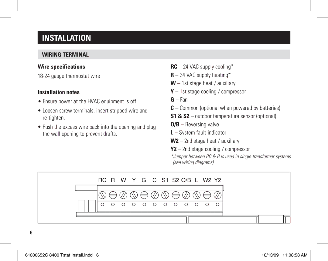
In terms of installation, the Aprilaire 61000652C is designed for easy mounting on walls and includes comprehensive installation instructions, ensuring that even those with minimal experience can set it up with ease.
Overall, the Aprilaire 61000652C 8400 T-stat combines user-friendly features, advanced technology, and energy-efficient capabilities, making it an exceptional choice for modern home comfort management. Whether you’re a homeowner looking to optimize your indoor climate or seeking to enhance your HVAC system's efficiency, this thermostat rises to the occasion with its robust functionalities.