| TROUBLESHOOTING | |
SYMPTOM | CAUSE | |
Normal Flashing LED not flashing | No power to control panel - check power wiring | |
No Heat call or Cool call | - TSTATS not operating properly. If Zone 1 is set up as a heat pump thermostat, it requires an O + Yfor cool call | |
and Y for a heat call. | ||
| ||
| - 4 minute minimum off time delay in effect - push TDO | |
| - Missing jumper between equipment RH&RC - required for single transformer systems | |
| - Equipment interrupt due to high/low temperature limit | |
| - Heat/Cool Changeover limit in effect and an opposing call is being answered in another zone | |
Won't stop calling | Minimum on time delay in effect (2 minutes for heat, 4 minutes for cool) | |
Heat calls being satisfied with Emergency Heat | - Heat Pump TSTAT installed in Zone 1: If Zone 1 is in Emergency Heat mode, all heat calls from other zones will be | |
| satisfied with Emergency Heat until Zone 1 makes a compressor call (normal heat or cool call). | |
| - Onboard | |
No Emergency Heat Call | - Zone 1 W terminal not energized or energized with Y terminal | |
| - Onboard | |
|
|
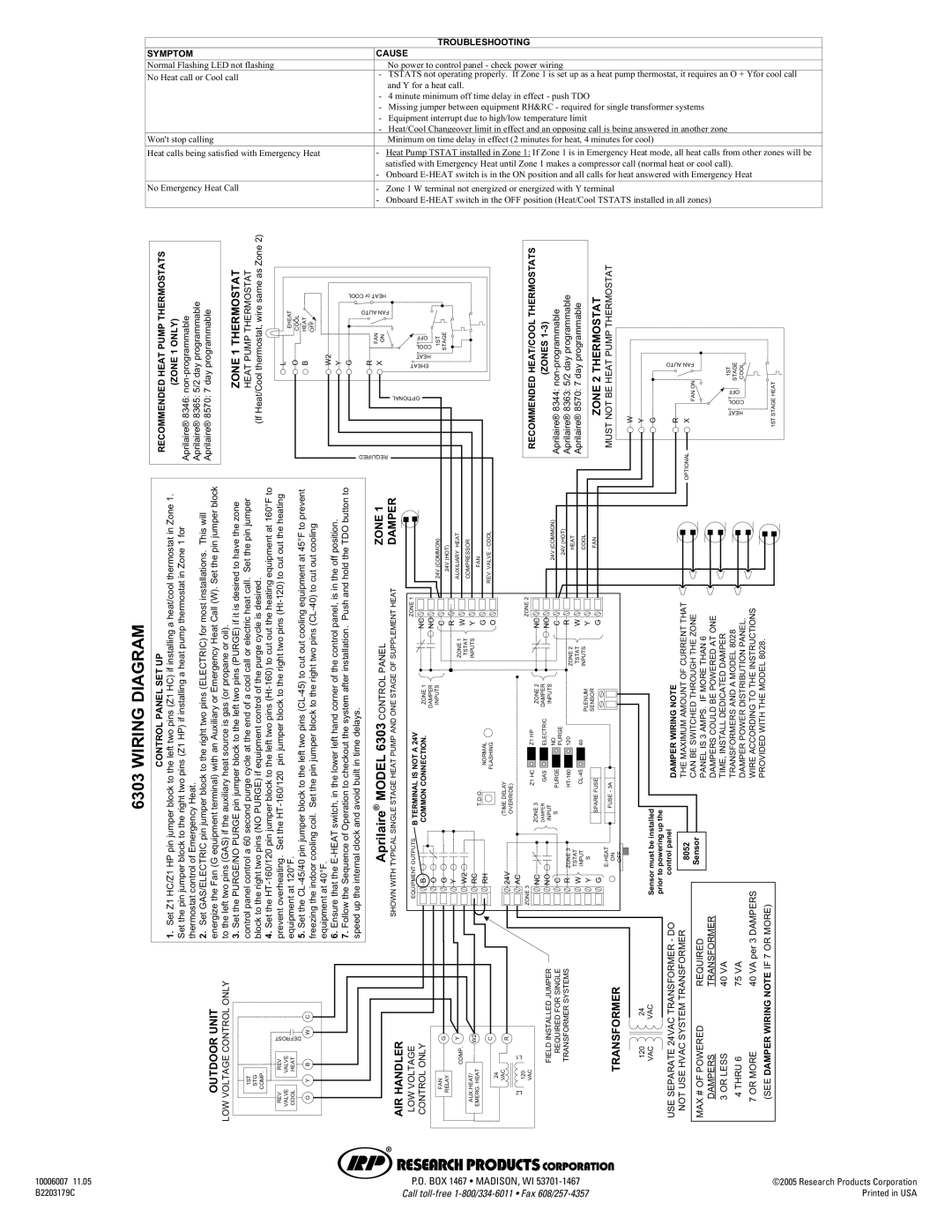
6303 WIRING DIAGRAM
RECOMMENDED HEAT PUMP THERMOSTATS | (ZONE 1 ONLY) Aprilaire® 8346: |
CONTROL PANEL SET UP | 1. Set Z1 HC/Z1 HP pin jumper block to the left two pins (Z1 HC) if installing a heat/cool thermostat in Zone 1. Set the pin jumper block to the right two pins (Z1 HP) if installing a heat pump thermostat in Zone 1 for thermostat control of Emergency Heat. 2. Set GAS/ELECTRIC pin jumper block to the right two pins (ELECTRIC) for most installations. This will energize the Fan (G equipment terminal) with an Auxiliary or Emergency Heat Call (W). Set the pin jumper block |
OUTDOOR UNIT
LOW VOLTAGE CONTROL ONLY to the left two pins (GAS) if the auxiliary heat source is gas (or propane or oil).
|
| Zone 2) |
|
|
|
|
|
|
|
ZONE 1 THERMOSTAT | HEAT PUMP THERMOSTAT | Heat/Cool thermostat, wire same as |
|
| COOL or HEAT |
|
|
| |
EHEAT COOL |
|
| AUTO FAN |
|
|
| |||
|
|
|
|
|
| ||||
L O B HEAT | OFF |
| FAN ON | OFF | 1ST | STAGE | |||
|
| ||||||||
|
| COOL | |||||||
W2 Y G | R X | HEAT | |||||||
EHEAT | |||||||||
OPTIONAL | |||||||||
| |||||||||
|
| (If |
|
|
|
|
|
|
|
|
|
|
|
|
| REQUIRED |
|
|
|
thetoblockjumperpinPURGEPURGE/NOtheSet3.left two pins (PURGE) if it is desired to have the zone endtheatcyclepurgesecond60acontrolpanelcontrolof a cool call or electric heat call. Set the pin jumper | controlequipmentifPURGE)(NOpinstworightthetoblock of the purge cycle is desired. | 120°F.atequipment | 40°F.atequipment | systemthecheckouttoOperationofSequencetheFollow7. after installation. Push and hold the TDO button to delays.timeinbuiltavoidandclockinternaltheupspeed | Aprilaire | ANDPUMPHEATSTAGESINGLETYPICALWITHSHOWNONE STAGE OF SUPPLEMENT HEATDAMPER | OUTPUTSEQUIPMENT | CONNECTION.COMMONB ZONE 1 | O | G | Y | W2 | RC | RHNORMAL FLASHING |
|
|
|
|
| 1ZONE |
|
|
| (COMMON)24V | (HOT)24V | HEATAUXILIARY | COMPRESSOR | FAN | COOL-VALVEREV. |
|
|
|
|
|
|
| 1ZONE |
|
|
|
|
|
|
|
|
|
|
|
|
|
| NC NO C R W Y G O | |||||||
|
|
|
|
| PANEL |
|
|
|
|
| 1ZONE TSTAT INPUTS |
| ||
|
|
|
|
| CONTROL |
|
|
| DAMPER INPUTS |
|
|
|
|
|
|
|
|
|
| 6303 |
| A 24V |
|
|
|
|
|
|
|
|
|
|
|
| MODEL |
| IS NOT |
|
|
|
|
|
|
|
|
|
|
|
| ® |
| TERMINAL |
|
|
|
|
| T.D.O. | |
|
|
|
|
|
|
| B |
|
|
|
|
|
|
|
|
| C |
|
|
|
|
|
| DEFROST | W | AIR HANDLER LOW VOLTAGE CONTROL ONLY | G | Y | W2 | C |
1ST STG COMP. | REV REV VALVE VALVE COOL HEAT | O Y B | FAN RELAY | COMP. | AUX.HEAT/ EMERG. HEAT | 24 |
RECOMMENDEDTHERMOSTATSHEAT/COOL | (ZONES3)1- | Aprilaire®programmable8344: non- | Aprilaire®programmable8363: 5/2day Aprilaire®programmable8570: 7 day | THERMOSTATZONE 2 | MUSTTHERMOSTATNOT BEPUMPHEAT |
| AUTO FAN | 1ST | STAGE COOL | |
| R OPTIONAL X FAN ON | |||||||||
| OFF | |||||||||
| COOL | |||||||||
| HEAT | |||||||||
W Y G |
| STAGEHEAT1ST | ||||||||
|
| 24V (COMMON) | 24V (HOT) HEAT | COOL | FAN |
|
|
|
|
|
|
| 2 |
|
|
|
|
|
|
|
|
|
|
|
|
|
|
|
|
|
|
|
|
|
|
|
| |
DELAY(TIME OVERRIDE) |
| ZONE | HCZ1HPZ1 | ELECTRICGAS |
| PURGE | ZONE 2 |
| SENSOR |
| 3A |
|
| installedbemust | the | DAMPERWIRING NOTE | AMOUNTMAXIMUMTHE OF CURRENT THAT | SWITCHEDBECANTHROUGH THE ZONE IFAMPS.3ISPANELMORE THAN 6 | INSTALLTIME, DEDICATED DAMPER | TRANSFORMERSAND A MODEL 8028 DAMPERPOWER DISTRIBUTION PANEL. | ACCORDINGWIRE TO THE INSTRUCTIONS | PROVIDEDWITH THE MODEL 8028. | |||||
| 3ZONE | DAMPER INPUT | S | TSTAT INPUT |
| FUSESPARE | ON OFF |
| 8052 | Sensor | POWEREDDAMPERSCOULDONEBEAT | ||||||||||||||||
|
|
|
| NC | NO | C | R |
| W | Y G |
|
|
|
|
|
|
|
|
|
|
|
|
|
| |||
|
|
|
|
|
|
|
|
|
| TSTAT INPUTS |
|
|
|
|
|
|
|
|
|
|
|
|
|
|
|
| |
|
|
|
| 2ZONE | DAMPER | INPUTS |
|
|
| PLENUM |
|
|
|
|
|
|
|
|
|
|
|
|
|
|
|
| |
|
|
|
|
|
| NO PURGE |
|
|
|
|
|
|
|
|
|
|
|
|
|
|
|
|
|
|
|
| |
|
|
| VAC NC | JUMPERINSTALLEDFIELD | SINGLEFORREQUIREDC | SYSTEMSTRANSFORMER |
|
|
|
|
| FUSE - | TRANSFORMER |
|
|
| TRANSFORMER24VACSEPARATEUSE - DO control panel | TRANSFORMERSYSTEMHVACUSENOT |
| REQUIREDPOWEREDOF#MAX | TRANSFORMERDAMPERS | 40LESSOR3VA | 756THRU4VA | 40MOREOR7VA per 3 DAMPERS | NOTEWIRINGDAMPER(SEEIF 7 OR MORE) | ||
VAC |
|
|
| W | Y S | G | 12024 | VACVAC | prior to powering up |
| |||||||||||||||||
24V | AC | ZONE3 | NO |
| R |
|
|
|
|
|
|
|
| Sensor |
|
|
|
|
|
|
|
|
|
| |||
R |
|
|
|
|
|
|
|
|
|
|
|
|
|
|
|
|
|
|
|
|
|
|
|
|
|
|
|
| L1 |
|
|
|
|
|
|
|
|
|
|
|
|
|
|
|
|
|
|
|
|
|
|
|
|
|
|
| 120 |
|
|
|
|
|
|
|
|
|
|
|
|
|
|
|
|
|
|
|
|
|
|
|
|
| |
| L2 |
|
|
|
|
|
|
|
|
|
|
|
|
|
|
|
|
|
|
|
|
|
|
|
|
|
|
10006007 11.05 | P.O. BOX 1467 • MADISON, WI | ©2005 Research Products Corporation |
B2203179C | Call | Printed in USA |