2. MOUNT THE 8052 PLENUM TEMPERATURE SENSOR (provided)
IMPORTANT: Do not mount the sensor in direct
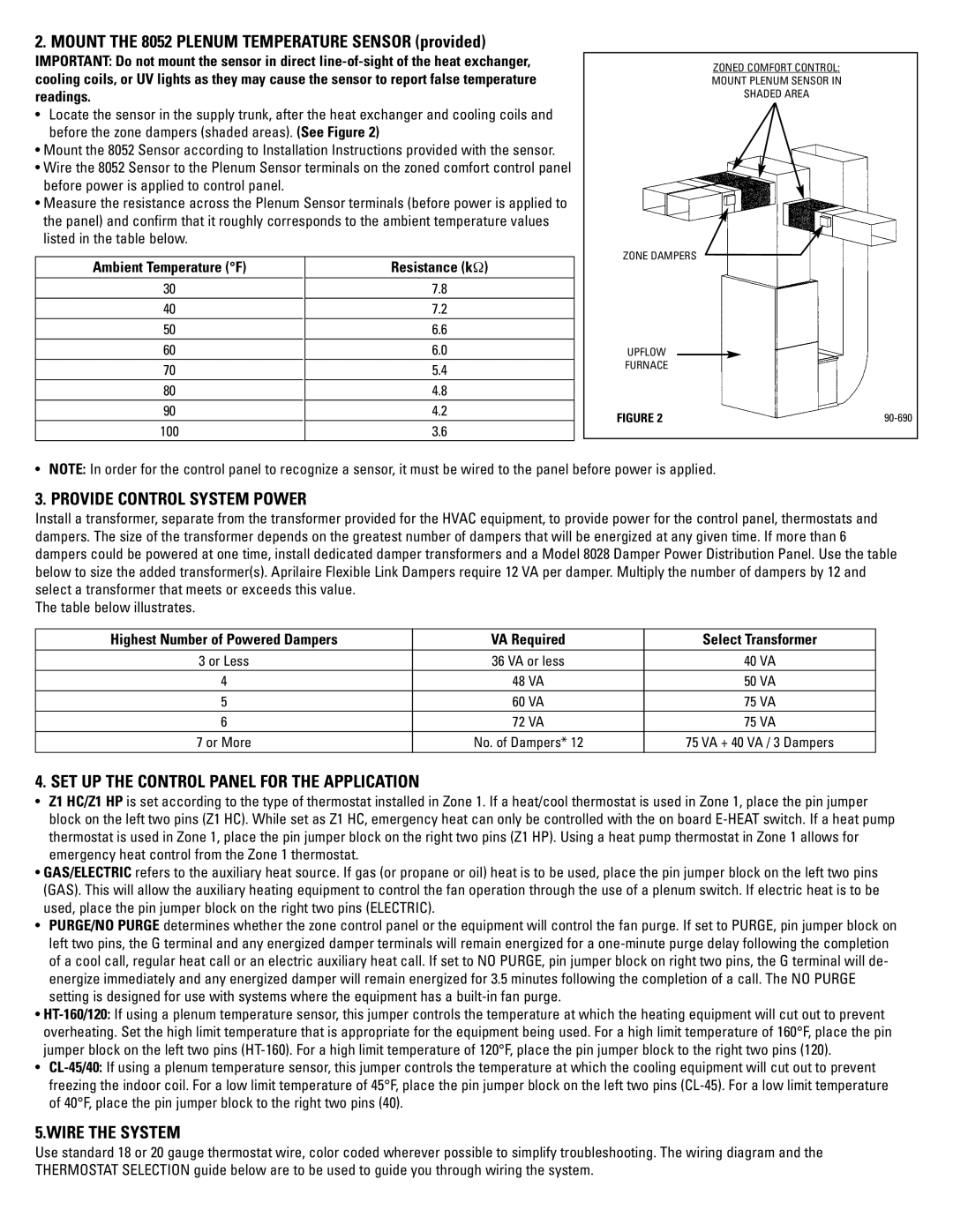
•Locate the sensor in the supply trunk, after the heat exchanger and cooling coils and before the zone dampers (shaded areas). (See Figure 2)
•Mount the 8052 Sensor according to Installation Instructions provided with the sensor.
•Wire the 8052 Sensor to the Plenum Sensor terminals on the zoned comfort control panel before power is applied to control panel.
•Measure the resistance across the Plenum Sensor terminals (before power is applied to the panel) and confirm that it roughly corresponds to the ambient temperature values listed in the table below.
Ambient Temperature (°F) | Resistance (kΩ) |
30 | 7.8 |
40 | 7.2 |
50 | 6.6 |
60 | 6.0 |
70 | 5.4 |
80 | 4.8 |
90 | 4.2 |
100 | 3.6 |
ZONED COMFORT CONTROL:
MOUNT PLENUM SENSOR IN
SHADED AREA
ZONE DAMPERS
UPFLOW
FURNACE
FIGURE 2 |
• NOTE: In order for the control panel to recognize a sensor, it must be wired to the panel before power is applied.
3. PROVIDE CONTROL SYSTEM POWER
Install a transformer, separate from the transformer provided for the HVAC equipment, to provide power for the control panel, thermostats and dampers. The size of the transformer depends on the greatest number of dampers that will be energized at any given time. If more than 6 dampers could be powered at one time, install dedicated damper transformers and a Model 8028 Damper Power Distribution Panel. Use the table below to size the added transformer(s). Aprilaire Flexible Link Dampers require 12 VA per damper. Multiply the number of dampers by 12 and select a transformer that meets or exceeds this value.
The table below illustrates.
Highest Number of Powered Dampers | VA Required | Select Transformer |
|
|
|
3 or Less | 36 VA or less | 40 VA |
4 | 48 VA | 50 VA |
5 | 60 VA | 75 VA |
6 | 72 VA | 75 VA |
7 or More | No. of Dampers* 12 | 75 VA + 40 VA / 3 Dampers |
|
|
|
4. SET UP THE CONTROL PANEL FOR THE APPLICATION
•Z1 HC/Z1 HP is set according to the type of thermostat installed in Zone 1. If a heat/cool thermostat is used in Zone 1, place the pin jumper block on the left two pins (Z1 HC). While set as Z1 HC, emergency heat can only be controlled with the on board
•GAS/ELECTRIC refers to the auxiliary heat source. If gas (or propane or oil) heat is to be used, place the pin jumper block on the left two pins (GAS). This will allow the auxiliary heating equipment to control the fan operation through the use of a plenum switch. If electric heat is to be used, place the pin jumper block on the right two pins (ELECTRIC).
•PURGE/NO PURGE determines whether the zone control panel or the equipment will control the fan purge. If set to PURGE, pin jumper block on left two pins, the G terminal and any energized damper terminals will remain energized for a
•
•
5.WIRE THE SYSTEM
Use standard 18 or 20 gauge thermostat wire, color coded wherever possible to simplify troubleshooting. The wiring diagram and the THERMOSTAT SELECTION guide below are to be used to guide you through wiring the system.