UNDER CARRIAGE

TO


RTD 3


TERM BLK


TO


TERM BLK


RTD 2


15


RTD 1


L2

3


3


6


RTD


L1

14


AN1


WHITE (-)


RED (+)


24


7


AN2


BLACK (-)


7


7


AN3

M. CTL.


30


21

(P6 "-")

21

I/O 3


(P9 "+")

22


25


22


(P11 "-")

19

2


RTD 2


20

(P15 "+")

20

I/O


RTD 1


17

(P16 "-")

17

1


18

(P20 "+")

18

I/O


TO


6


ZONE 3

22


L2/N


TERM BLK


9

T1

+ A1


25


15


TO


WHT


-A2

21


6


TERM BLK

1


8

L1


L1


SEE


RTD


DETAIL


3


VIEW


SCOTCHLOCK

23

4

RED/BROWN


ZONE 2


BLACK/BLUE

TO


RED


16


7


T1

+ A1

20


TERM BLK


31


SCOTCHLOCK


8

L1

-A2

19


BLK


24


BLACK


14


WHITE


RED


ZONE 1


3


OR


BLUE


T1

+ A1

18


GR


GREEN


BL


ORANGE


MOTOR


1


RTD


3

L1

- A2

17


31


CONTACTOR

29

28


A2

A1


7


32


4

5


3


7

T1/2

1/L1


TO: TERMINAL BLK L1


24


24


23

2


T2/4

3/L2


TO: TERMINAL BLK L2


32 T3/6

5/L3

BLK


TO:


14

13/NO

28


TEMP


22

21/NC


PROBE RTD1


RED


TO:


OR

GR

BL


ELEMENT 13


RIGHT SIDE


29

30

TO:


HOUSING


MOTOR SPEED POT.


ELEMENT

14


POWER SWITCH


ESCUTCHEON


LEFT SIDE HOUSING

1 T.STAT


2 L2

1

L2


26


5


L1


L1


L1

L2


2


T.STAT

GR


26


POWER CORD


L1= BLACK


2

5

L2= WHITE


TO: POWER


SWITCH


RIGHT SIDE HOUSING

CONTROLLER

TERMINAL BLOCK

RELAY

TO SPEED

TO SPEED

TO SPEED


TO

TO

TO

MOTOR-ORANGE

MOTOR-GREEN MOTOR-BLUE


TO POWER SUPPLY


TO CONTACTOR "A2"

6 PIN-RED


RTD 1


LOWER HEATER ZONE


BL GR

OR


29

30


MOTOR SPEED POT.

POWER SWITCH


ESCUTCHEON


RIGHT SIDE


HOUSING


11


Page 11
Image 11
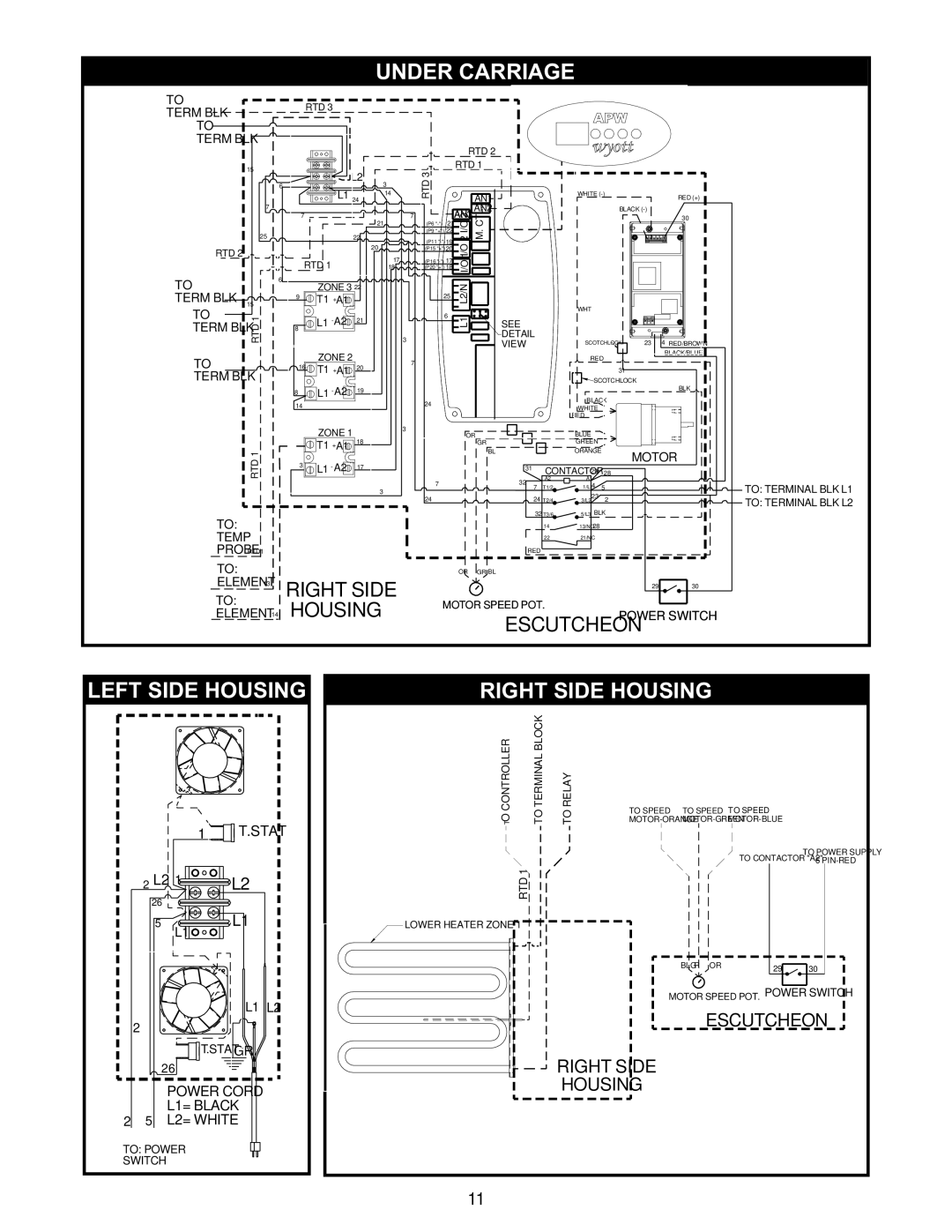
APW Wyott XWAV1417, XWAV1829, XWAV1422 manual Under Carriage, Left Side Housing, Right Side Housing

XWAV1417, XWAV1422, XWAV1829 specifications

APW Wyott is a renowned name in the food service equipment industry, offering an extensive range of products designed to meet the demands of commercial kitchens. Among their impressive lineup are the XWAV1829, XWAV1422, and XWAV1417 models, each designed with unique features and technologies that enhance performance, efficiency, and safety.

The APW Wyott XWAV1829 is a state-of-the-art heated holding cabinet that excels in maintaining food temperature without compromising quality. One of its standout features is the adjustable humidity control, allowing operators to create the ideal environment for different types of food. This model is equipped with a digital thermostat that ensures precise temperature settings, providing peace of mind that food is held at safe levels. The cabinet is constructed from durable stainless steel, promoting longevity and ease of cleaning. With a spacious interior, the XWAV1829 can accommodate a variety of food pans, making it versatile for different kitchen needs.

The XWAV1422 model follows suit with its innovative design tailored for efficiency. Featuring the same robust stainless steel construction, it is built to withstand the rigors of a busy kitchen. This model also boasts a clear door, allowing for quick visibility of contents without opening the cabinet, thus preserving heat and humidity. The user-friendly digital controls make temperature adjustments a breeze, and its compact design is perfect for kitchens with limited space. Additionally, it's equipped with energy-efficient heating elements, ensuring lower operational costs.

Finally, the APW Wyott XWAV1417 is designed for optimized performance and durability. Incorporating advanced technology, it offers precise temperature control and even heat distribution, ensuring that food is kept at the ideal temperature throughout meal service. This model also includes easy-to-read LED indicators, providing clear visibility of the holding status. The well-insulated design minimizes heat loss, further enhancing energy efficiency.

In summary, the XWAV1829, XWAV1422, and XWAV1417 models bring together cutting-edge technologies and robust features that cater to the needs of modern kitchens. From adjustable humidity and digital thermostats to energy-efficient heating, each model stands as a testament to APW Wyott's commitment to quality and performance. These heated holding cabinets are indispensable for any food service operation aiming to maintain food safety and quality.