GAS CONNECTIONS and Gas Regulator
NOTE: The Aquastar 125 B”S” is supplied with a gas pressure regulator that must be installed on the heater before attaching the gas supply line. See figure 5. Failure to install the gas regulator as shown in figure 5 will be a violation of CSA certification of the unit. The regulator supplied with the heater is preset for the gas shown on the rating plate to the correct pressure. It is an appliance level regulator designed for (low inlet) pressure (less than 1/2 Psig or 15” W.C.) DO NOT connect to an unregulated or high pressure propane line or to a high pressure commercial natural gas line.
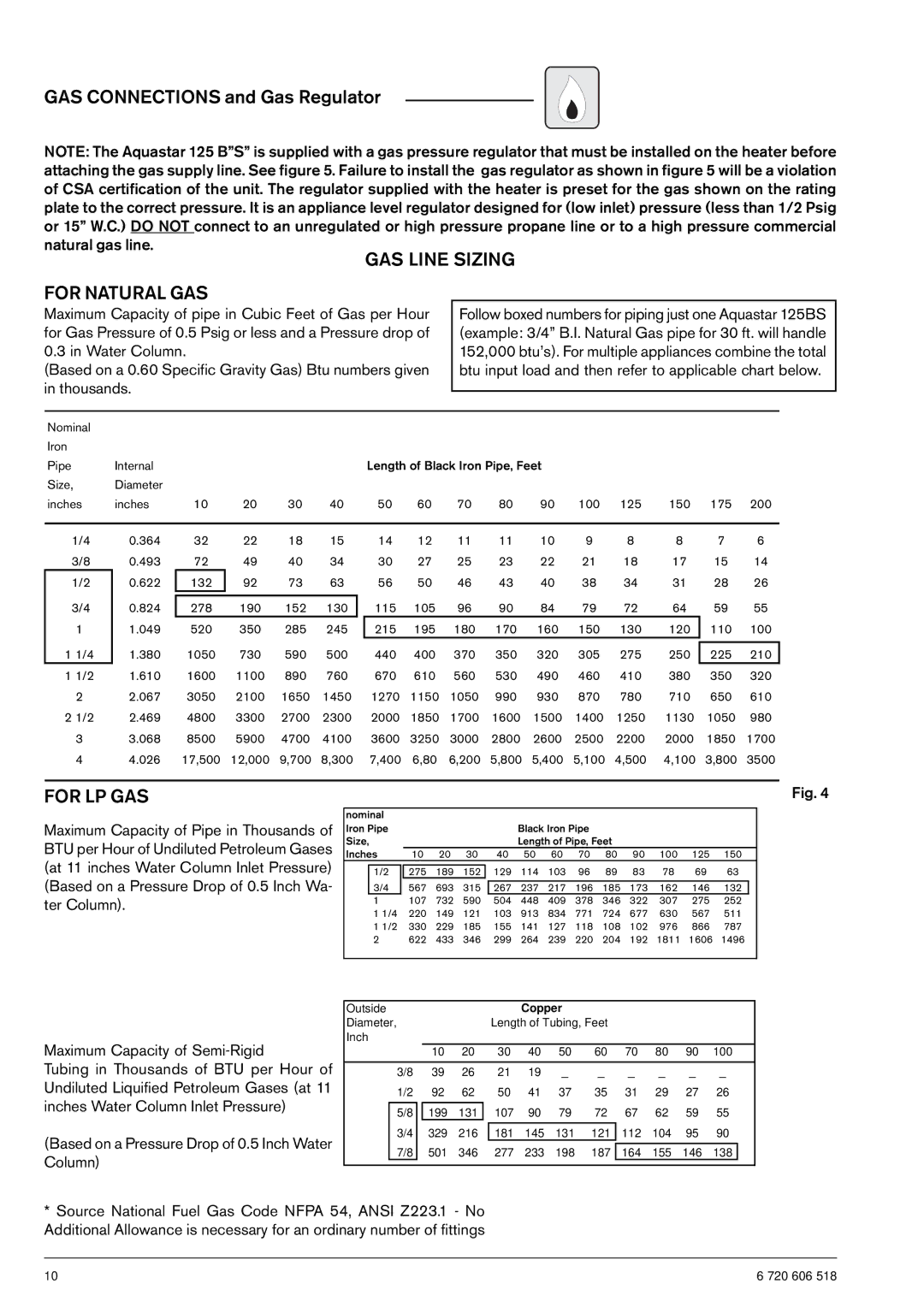
GAS LINE SIZING
FOR NATURAL GAS
Maximum Capacity of pipe in Cubic Feet of Gas per Hour for Gas Pressure of 0.5 Psig or less and a Pressure drop of 0.3 in Water Column.
(Based on a 0.60 Specific Gravity Gas) Btu numbers given in thousands.
Follow boxed numbers for piping just one Aquastar 125BS (example: 3/4” B.I. Natural Gas pipe for 30 ft. will handle 152,000 btu’s). For multiple appliances combine the total btu input load and then refer to applicable chart below.
Nominal |
|
|
|
|
|
|
|
|
|
|
|
|
Iron |
|
|
|
|
|
|
|
|
|
|
|
|
Pipe | Internal |
|
|
|
| Length of Black Iron Pipe, Feet |
|
| ||||
Size, | Diameter |
|
|
|
|
|
|
|
|
|
|
|
inches | inches | 10 | 20 | 30 | 40 | 50 | 60 | 70 | 80 | 90 | 100 125 | 150 175 200 |
1/4
3/8
1/2
3/4
1
11/4
11/2
2
21/2
3
4
0.364
0.493
0.622
0.824
1.049
1.380
1.610
2.067
2.469
3.068
4.026
32 | 22 | 18 | 15 |
72 | 49 | 40 | 34 |
132 | 92 | 73 | 63 |
|
|
|
|
278 | 190 | 152 | 130 |
520 | 350 | 285 | 245 |
1050 | 730 | 590 | 500 |
1600 | 1100 | 890 | 760 |
3050 | 2100 | 1650 | 1450 |
4800 | 3300 | 2700 | 2300 |
8500 | 5900 | 4700 | 4100 |
17,500 | 12,000 | 9,700 | 8,300 |
14 | 12 | 11 | 11 | 10 | 9 | 8 | 8 | 7 | 6 |
30 | 27 | 25 | 23 | 22 | 21 | 18 | 17 | 15 | 14 |
56 | 50 | 46 | 43 | 40 | 38 | 34 | 31 | 28 | 26 |
115 | 105 | 96 | 90 | 84 | 79 | 72 | 64 | 59 | 55 |
215 | 195 | 180 | 170 | 160 | 150 | 130 | 120 | 110 | 100 |
|
|
|
|
|
|
|
|
|
|
440 | 400 | 370 | 350 | 320 | 305 | 275 | 250 | 225 | 210 |
670 | 610 | 560 | 530 | 490 | 460 | 410 | 380 | 350 | 320 |
1270 | 1150 | 1050 | 990 | 930 | 870 | 780 | 710 | 650 | 610 |
2000 | 1850 | 1700 | 1600 | 1500 | 1400 | 1250 | 1130 | 1050 | 980 |
3600 | 3250 | 3000 | 2800 | 2600 | 2500 | 2200 | 2000 | 1850 | 1700 |
7,400 | 6,80 | 6,200 | 5,800 | 5,400 | 5,100 | 4,500 | 4,100 | 3,800 | 3500 |
FOR LP GAS
Maximum Capacity of Pipe in Thousands of BTU per Hour of Undiluted Petroleum Gases (at 11 inches Water Column Inlet Pressure) (Based on a Pressure Drop of 0.5 Inch Wa- ter Column).
Fig. 4
nominal |
|
|
|
|
|
|
|
|
|
|
|
|
|
| |
Iron Pipe |
|
|
|
|
| Black Iron Pipe |
|
|
|
|
|
| |||
Size, |
|
|
|
|
| Length of Pipe, Feet |
|
|
|
|
| ||||
Inches | 10 | 20 | 30 | 40 | 50 | 60 | 70 | 80 | 90 | 100 | 125 | 150 |
| ||
|
|
|
|
| 129 | 114 | 103 | 96 | 89 | 83 | 78 | 69 | 63 |
| |
| 1/2 | 275 | 189 | 152 |
| ||||||||||
| 3/4 | 567 | 693 | 315 |
|
|
|
|
|
|
|
|
|
| |
|
| 267 | 237 | 217 | 196 | 185 | 173 | 162 | 146 | 132 |
| ||||
| 1 | 107 | 732 | 590 |
| 504 | 448 | 409 | 378 | 346 | 322 | 307 | 275 | 252 |
|
1 1/4 | 220 | 149 | 121 | 103 | 913 | 834 | 771 | 724 | 677 | 630 | 567 | 511 |
| ||
1 1/2 | 330 | 229 | 185 | 155 | 141 | 127 | 118 | 108 | 102 | 976 | 866 | 787 |
| ||
2 | 622 | 433 | 346 | 299 | 264 | 239 | 220 | 204 | 192 | 1811 | 1606 | 1496 |
| ||
|
|
|
|
|
|
|
|
|
|
|
|
|
|
|
|
| Outside |
|
|
|
|
| Copper |
|
|
|
|
|
| ||
| Diameter, |
|
|
|
| Length of Tubing, Feet |
|
|
|
|
| ||||
Maximum Capacity of | Inch |
|
|
|
|
|
|
|
|
|
|
|
|
| |
|
| 10 | 20 | 30 | 40 | 50 | 60 | 70 | 80 | 90 | 100 |
| |||
Tubing in Thousands of BTU per Hour of |
|
|
|
|
|
|
|
|
|
|
|
| |||
3/8 | 39 | 26 | 21 | 19 | _ | _ | _ | _ | _ | _ |
| ||||
Undiluted Liquified Petroleum Gases (at 11 | 1/2 | 92 | 62 | 50 | 41 | 37 | 35 | 31 | 29 | 27 | 26 |
| |||
inches Water Column Inlet Pressure) |
|
|
|
|
|
|
|
|
|
|
|
|
|
|
|
| 5/8 |
| 199 | 131 | 107 | 90 | 79 | 72 | 67 | 62 | 59 | 55 |
| ||
|
|
|
| ||||||||||||
|
|
|
|
|
|
|
|
|
|
|
|
|
|
|
|
(Based on a Pressure Drop of 0.5 Inch Water |
| 3/4 | 329 | 216 |
| 181 | 145 | 131 | 121 | 112 | 104 | 95 | 90 |
| |
|
|
|
|
|
|
|
|
|
|
|
|
|
|
| |
| 7/8 | 501 | 346 | 277 | 233 | 198 | 187 | 164 | 155 | 146 | 138 |
| |||
Column) |
|
| |||||||||||||
|
|
|
|
|
|
|
|
|
|
|
|
|
|
| |
|
|
|
|
|
|
|
|
|
|
|
|
|
|
| |
*Source National Fuel Gas Code NFPA 54, ANSI Z223.1 - No Additional Allowance is necessary for an ordinary number of fittings
10 | 6 720 606 518 |