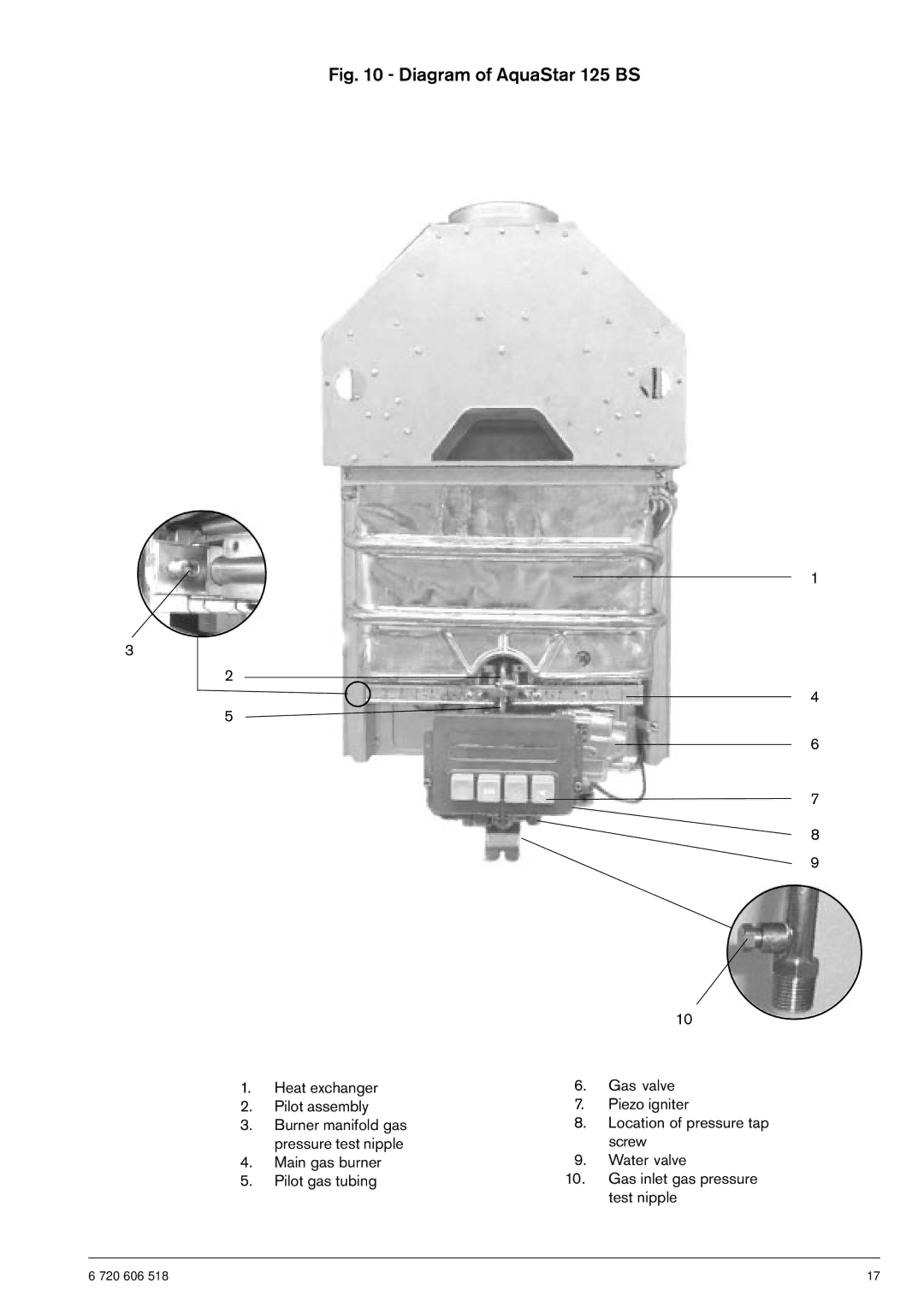
Fig. 10 - Diagram of AquaStar 125 BS
3
2
5
1.Heat exchanger
2.Pilot assembly
3.Burner manifold gas pressure test nipple
4.Main gas burner
5.Pilot gas tubing
1
4
6
7
8
9
10
6.Gas valve
7.Piezo igniter
8.Location of pressure tap screw
9.Water valve
10.Gas inlet gas pressure test nipple
6 720 606 518 | 17 |