COMBUSTION AIR REQUIREMENT | CLEARANCES |
The AquaStar water heater holds cold water in its copper heat exchanger and brass water valve when not in use. Because of this, any cold air that comes in through the unit’s vent pipe is capable of freezing these components. This Installation Manual specifies the minimum vertical vent pipe and the amount of combustion air required for this unit. When all requirements are followed, the unit will operate properly and safely. However, there may still be a risk of freezing due to negative draft if all the combustion appliances in the area are not being supplied with a sufficient amount of
Observe the following instructions concerning combustion air.
Appliances located in confined spaces:
The confined space must be provided with two permanent openings, one commencing within 12 inches of the top and one commencing within 12 inches of the bottom of the enclosure. Each opening must have a minimum free area of one square inch per:
-1000 Btu/hr if all air is taken from inside the building.
-2000 Btu/hr if all air is taken from the outside by horizontal ducts.
-4000 Btu/hr if all air is taken from the outside by direct openings or vertical ducts.
Or the confined space must be provided with one permanent opening or duct that is within 12 inches of the ceiling of the enclosure. This opening must have a minimum free area of one square inch per:
Louvers, grills and screens have a blocking effect. If the effective free area is not known, increase the sizes of your openings by 75% if your louvers are wood and by 30% if your louvers are metal. Refer to the National Fuel Gas Code for complete information. In buildings of tight construction all air should be taken from outside. That would be 2000 cubic feet for the Aquastar 38B alone.
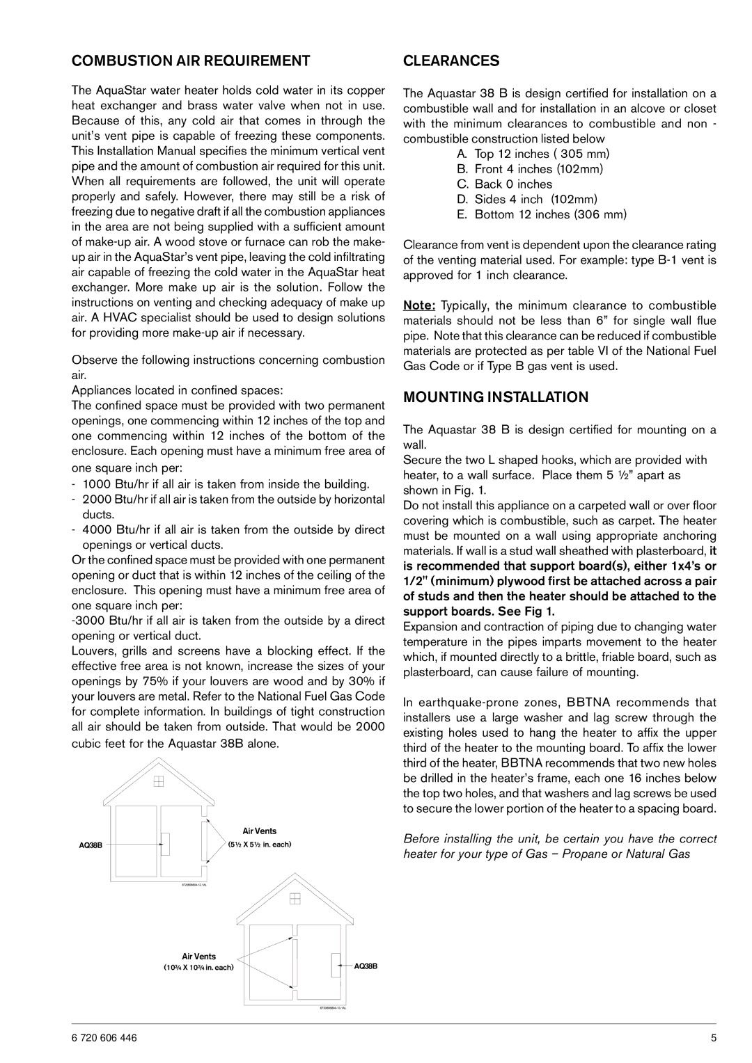
Air Vents
AQ38B |
| (5½ X 5½ in. each) |
|
Air Vents
(10¾ X 10¾ in. each) |
| AQ38B |
|
The Aquastar 38 B is design certified for installation on a combustible wall and for installation in an alcove or closet with the minimum clearances to combustible and non - combustible construction listed below
A.Top 12 inches ( 305 mm)
B.Front 4 inches (102mm)
C.Back 0 inches
D.Sides 4 inch (102mm)
E.Bottom 12 inches (306 mm)
Clearance from vent is dependent upon the clearance rating of the venting material used. For example: type
Note: Typically, the minimum clearance to combustible materials should not be less than 6” for single wall flue pipe. Note that this clearance can be reduced if combustible materials are protected as per table VI of the National Fuel Gas Code or if Type B gas vent is used.
MOUNTING INSTALLATION
The Aquastar 38 B is design certified for mounting on a wall.
Secure the two L shaped hooks, which are provided with heater, to a wall surface. Place them 5 ½” apart as shown in Fig. 1.
Do not install this appliance on a carpeted wall or over floor covering which is combustible, such as carpet. The heater must be mounted on a wall using appropriate anchoring materials. If wall is a stud wall sheathed with plasterboard, it is recommended that support board(s), either 1x4’s or 1/2" (minimum) plywood first be attached across a pair of studs and then the heater should be attached to the support boards. See Fig 1.
Expansion and contraction of piping due to changing water temperature in the pipes imparts movement to the heater which, if mounted directly to a brittle, friable board, such as plasterboard, can cause failure of mounting.
In
Before installing the unit, be certain you have the correct heater for your type of Gas – Propane or Natural Gas
6 720 606 446 | 5 |