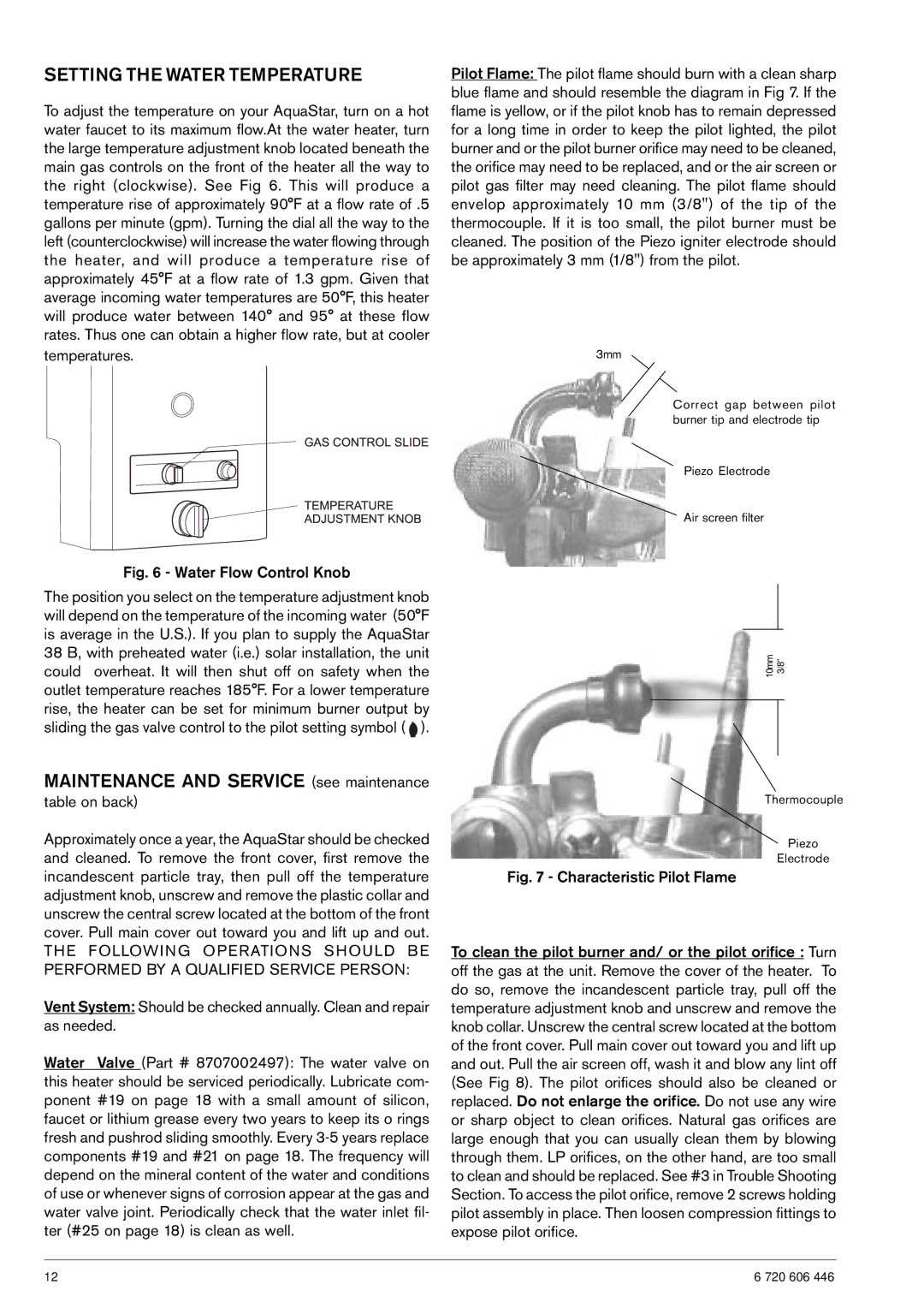
SETTING THE WATER TEMPERATURE
To adjust the temperature on your AquaStar, turn on a hot water faucet to its maximum flow.At the water heater, turn the large temperature adjustment knob located beneath the main gas controls on the front of the heater all the way to the right (clockwise). See Fig 6. This will produce a temperature rise of approximately 90°F at a flow rate of .5 gallons per minute (gpm). Turning the dial all the way to the left (counterclockwise) will increase the water flowing through the heater, and will produce a temperature rise of approximately 45°F at a flow rate of 1.3 gpm. Given that average incoming water temperatures are 50°F, this heater will produce water between 140° and 95° at these flow rates. Thus one can obtain a higher flow rate, but at cooler temperatures.
Fig. 6 - Water Flow Control Knob
The position you select on the temperature adjustment knob will depend on the temperature of the incoming water (50°F is average in the U.S.). If you plan to supply the AquaStar 38 B, with preheated water (i.e.) solar installation, the unit could overheat. It will then shut off on safety when the outlet temperature reaches 185°F. For a lower temperature rise, the heater can be set for minimum burner output by sliding the gas valve control to the pilot setting symbol ( ![]() ).
).
MAINTENANCE AND SERVICE (see maintenance
table on back)
Approximately once a year, the AquaStar should be checked and cleaned. To remove the front cover, first remove the incandescent particle tray, then pull off the temperature adjustment knob, unscrew and remove the plastic collar and unscrew the central screw located at the bottom of the front cover. Pull main cover out toward you and lift up and out.
TH E F OLLOWI N G O PE RATIONS SHOU LD B E PERFORMED BY A QUALIFIED SERVICE PERSON:
Vent System: Should be checked annually. Clean and repair as needed.
Water Valve (Part # 8707002497): The water valve on this heater should be serviced periodically. Lubricate com- ponent #19 on page 18 with a small amount of silicon, faucet or lithium grease every two years to keep its o rings fresh and pushrod sliding smoothly. Every
Pilot Flame: The pilot flame should burn with a clean sharp blue flame and should resemble the diagram in Fig 7. If the flame is yellow, or if the pilot knob has to remain depressed for a long time in order to keep the pilot lighted, the pilot burner and or the pilot burner orifice may need to be cleaned, the orifice may need to be replaced, and or the air screen or pilot gas filter may need cleaning. The pilot flame should envelop approximately 10 mm (3/8") of the tip of the thermocouple. If it is too small, the pilot burner must be cleaned. The position of the Piezo igniter electrode should be approximately 3 mm (1/8") from the pilot.
3mm
Correct gap between pilot burner tip and electrode tip
Piezo Electrode
Air screen filter
10mm | 3/8” |
|
|
|
|
Thermocouple
Piezo
Electrode
Fig. 7 - Characteristic Pilot Flame
To clean the pilot burner and/ or the pilot orifice : Turn off the gas at the unit. Remove the cover of the heater. To do so, remove the incandescent particle tray, pull off the temperature adjustment knob and unscrew and remove the knob collar. Unscrew the central screw located at the bottom of the front cover. Pull main cover out toward you and lift up and out. Pull the air screen off, wash it and blow any lint off (See Fig 8). The pilot orifices should also be cleaned or replaced. Do not enlarge the orifice. Do not use any wire or sharp object to clean orifices. Natural gas orifices are large enough that you can usually clean them by blowing through them. LP orifices, on the other hand, are too small to clean and should be replaced. See #3 in Trouble Shooting Section. To access the pilot orifice, remove 2 screws holding pilot assembly in place. Then loosen compression fittings to expose pilot orifice.
12 | 6 720 606 446 |