Aruba Networks FIPS 140-2 manual Aruba AP-125 TEL Placement, AP-124 Bottom view

Models: FIPS 140-2

1 36
Download 36 pages 13.37 Kb
Page 13
Image 13

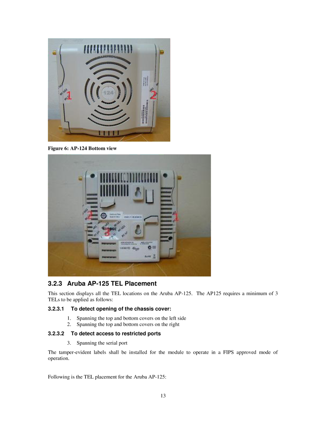
Figure 6: AP-124 Bottom view

3.2.3 Aruba AP-125 TEL Placement

This section displays all the TEL locations on the Aruba AP-125. The AP125 requires a minimum of 3 TELs to be applied as follows:

3.2.3.1To detect opening of the chassis cover:

1.Spanning the top and bottom covers on the left side

2.Spanning the top and bottom covers on the right

3.2.3.2To detect access to restricted ports

3.Spanning the serial port

The tamper-evident labels shall be installed for the module to operate in a FIPS approved mode of operation.

Following is the TEL placement for the Aruba AP-125:

13

Page 13
Image 13
Aruba Networks FIPS 140-2 manual Aruba AP-125 TEL Placement, AP-124 Bottom view