ifications

Architect'sSpecification

Ashly Model l5O0M

The power amplifier. being oftwo channels, shall deliver a minimum power oI 175 watts per channel into 8 ohm loads or 275 watts per channel into 4 ohm loads with both channels operating. When switched into bridged mono node. it shall deliver at least 550 watts into m 8 ohm load. The amplifier shall be immune to damage from shorted. open, or mismatched loads. The amplifier shall have a gain of 29dB t .5dB per channel and an input sen- sitiviqr of 1.3 Volts ! 20/olor lull rated output. Frequency response shall be 10Hz Io 2OkHz t .5d8. It shall be stable into any load including pure capacitors and inductors.

Hum and noise shall be at least 110d8 below full output and SMPTE intermodulation distoftion shall be less than

.010/oat full output. The amplifier shall have rear panel switching for mono and bridging modes and rear mounted level controls. The inputs shall be balanced bridging type with male and female XLR type connectors as well as 1/4" phone jacks. A three-color LED type indicator shall be employed to show the power level of each chamel and self contained forced air cooling shall be used. The power out-

put devlces shall be of the Lateral MOS FET fpe. The anplifier shall lveigh 371b. net and mount in a standard 19 inch rack using two spaces (3.5" high). The power requirement shall be 110 125VAC. 50 60H2.

The porver amplitier shall be an Ashly FET- 1500M.

Ashly Model 1500C

'Ile power amplilier, being of two channels, shall deliver a minimum power ol 175 watts per channel into 8 ohm loads or 275 watis per channel into 4 ohn loads wiLh both channcls operating. When switched into bridged mono mode. it shall deliver al leasi 550 watts into an 8 ohm load. The amplifier shnll be imntune to dam:rge liom shoried, open. or nisnratched loads. The amplifier shall have a gain oi29dB t .SdB per ch:rnnel and an input sen- sitivily of 1.3 Volts t 20/olor ltll rated output. F-requency response shall be 1OLIzto 2OkHz,t .5dts. It shall be stable inlo irny lo:rd inclllding pure capacitors and inductors. IIum :rnd noise shall bc at lcast I 1Odtsbelow llll output ancl SMPI'Eintermodulation clistortion shall be less than

.010/oat Iull output. Thc amplilier shall have rear panel swikrhing lbr rrono and bridgine modes and rear ntounted level controls. The inputs shall utilize 1/4' phonc.jacks as well as terminal/barricr input strips. Sell conLait.redlbrced

'l'he

air cooling shall be used. porver output dcvices shall be ol the Lateral MOS-FET type. The nmplilier shall weigh 371b. net and mouni in a stanclard l9 inch rack usinq two spaces (3.5'high), The power requirement shall be 110- l2SVAC. 50-60H2.

The power amplilier shall be an Ashly FET- I 500C.

Page 2
Image 2
Ashly FET-I500M, FET-I500C specifications Ifications, ArchitectsSpecification

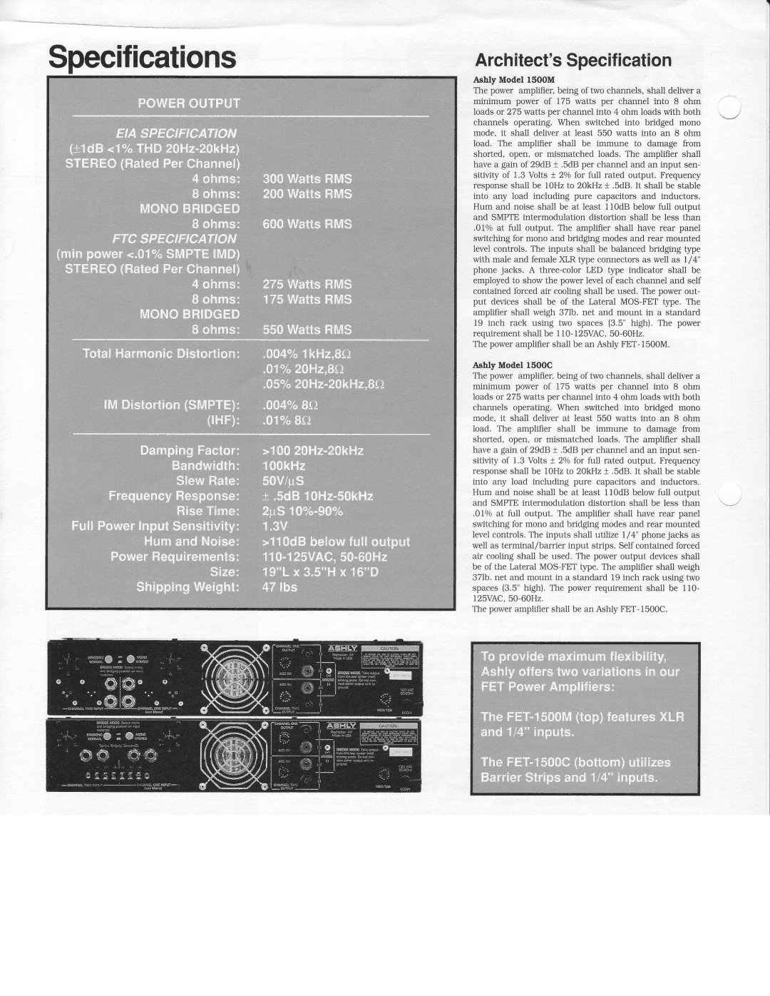
FET-I500C, FET-I500M specifications

The Ashly FET-I500C and FET-I500M are two power amplifiers that stand out in the audio industry for their innovative design, robust performance, and user-friendly features. These amplifiers are engineered to deliver high-quality sound in a variety of settings, making them ideal for everything from live sound reinforcement to installed systems in commercial spaces.

One of the key features of both the FET-I500C and FET-I500M is their Class D architecture. This design ensures high efficiency, which translates to less heat generation and lower power consumption. As a result, users can enjoy powerful audio outputs without the concerns associated with traditional amplifiers. The FET-I500C offers a power output of 500 watts per channel at 4 ohms, while the FET-I500M provides 500 watts at 8 ohms, making them versatile options for different speaker configurations.

Both models are equipped with extensive input options, including XLR, 1/4-inch TRS, and RCA connectors, allowing them to seamlessly integrate with various audio sources. Additionally, the amplifiers come with built-in signal processing capabilities, including high-pass and low-pass filters, which enable users to tailor the audio output to suit their particular needs. This level of control ensures optimal sound quality and enhanced performance, regardless of the environment.

The FET-I500C and FET-I500M also feature a rugged and lightweight design, which simplifies transport and installation. The external chassis is designed for durability, protecting the internal components from potential damage. Their fan-cooled system further ensures that the amplifiers stay within operational temperatures, thus enhancing longevity and reliability.

Moreover, these amplifiers are designed with user convenience in mind. They feature front-panel LED indicators that provide real-time feedback on power status, signal presence, and clipping. This user-friendly interface makes it easier for audio professionals to monitor performance during live events or installations.

In summary, the Ashly FET-I500C and FET-I500M amplifiers are impressive audio solutions that combine advanced technology with high performance. With their Class D architecture, extensive input flexibility, built-in processing capabilities, and robust, reliable design, these amplifiers are well-suited for a variety of audio applications, ensuring that users can achieve the best possible sound in any setting. Whether for live sound events or permanent installations, Ashly's FET-I500 series amplifiers are a reliable choice for audio professionals seeking exceptional quality and performance.