Page - 6 | Operator Manual – MQX Series Equalizers | |
|
|
|
Safety Instructions – 3
Introduction - 4
MQX Equalizers – 5
Connectors & Cables – 5
Physical Description - 6
Front Panels
Rear Panels
Installation – 7
Typical Applications - 8
Troubleshooting - 9
Dimensions - 9
Specifications - 10
Warranty - 11
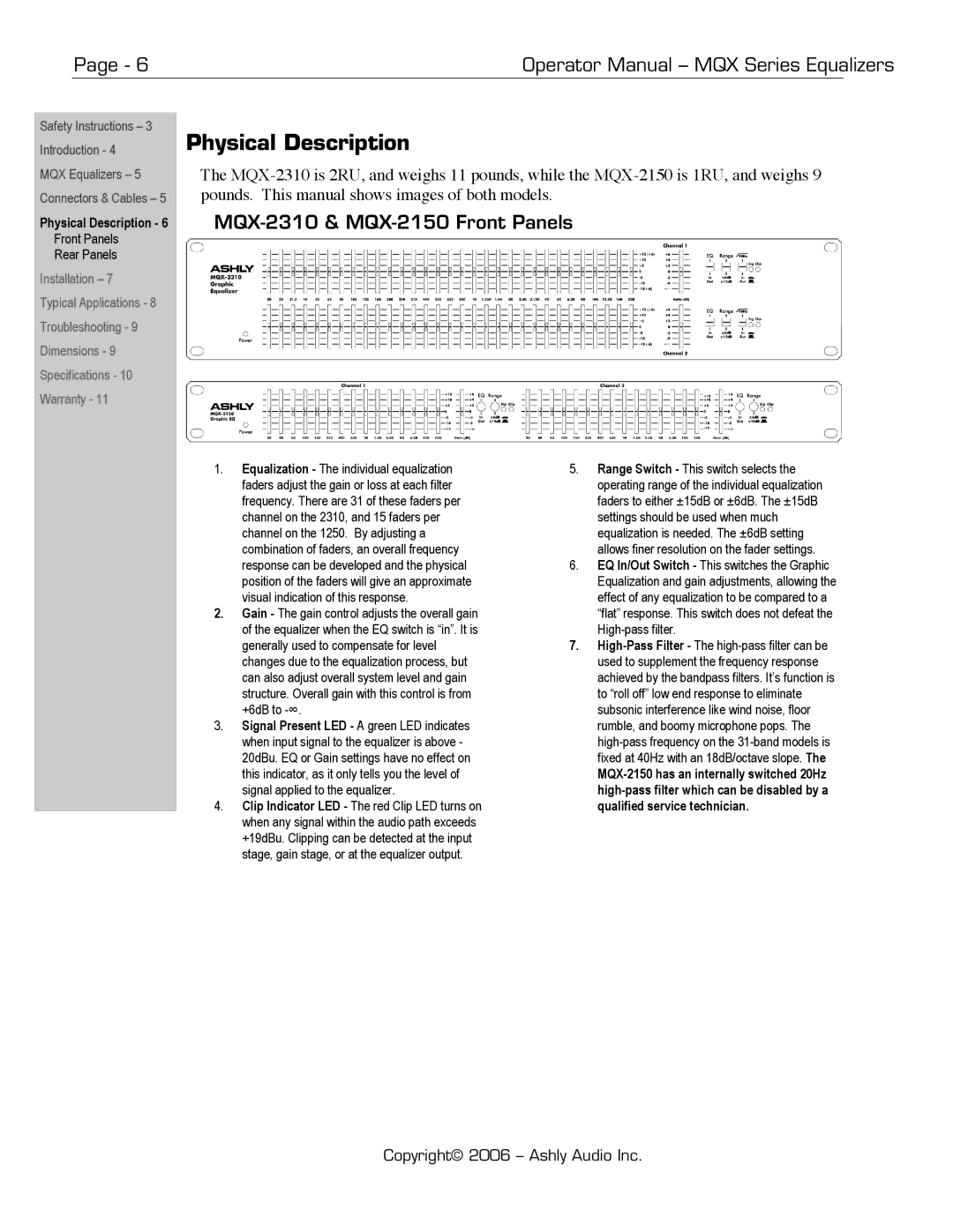
Physical Description
The
MQX-2310 & MQX-2150 Front Panels
1.Equalization - The individual equalization faders adjust the gain or loss at each filter frequency. There are 31 of these faders per channel on the 2310, and 15 faders per channel on the 1250. By adjusting a combination of faders, an overall frequency response can be developed and the physical position of the faders will give an approximate visual indication of this response.
2.Gain - The gain control adjusts the overall gain of the equalizer when the EQ switch is “in”. It is generally used to compensate for level changes due to the equalization process, but can also adjust overall system level and gain structure. Overall gain with this control is from +6dB to
3.Signal Present LED - A green LED indicates when input signal to the equalizer is above - 20dBu. EQ or Gain settings have no effect on this indicator, as it only tells you the level of signal applied to the equalizer.
4.Clip Indicator LED - The red Clip LED turns on when any signal within the audio path exceeds +19dBu. Clipping can be detected at the input stage, gain stage, or at the equalizer output.
5.Range Switch - This switch selects the operating range of the individual equalization faders to either ±15dB or ±6dB. The ±15dB settings should be used when much equalization is needed. The ±6dB setting allows finer resolution on the fader settings.
6.EQ In/Out Switch - This switches the Graphic Equalization and gain adjustments, allowing the effect of any equalization to be compared to a “flat” response. This switch does not defeat the
7.
Copyright© 2006 – Ashly Audio Inc.