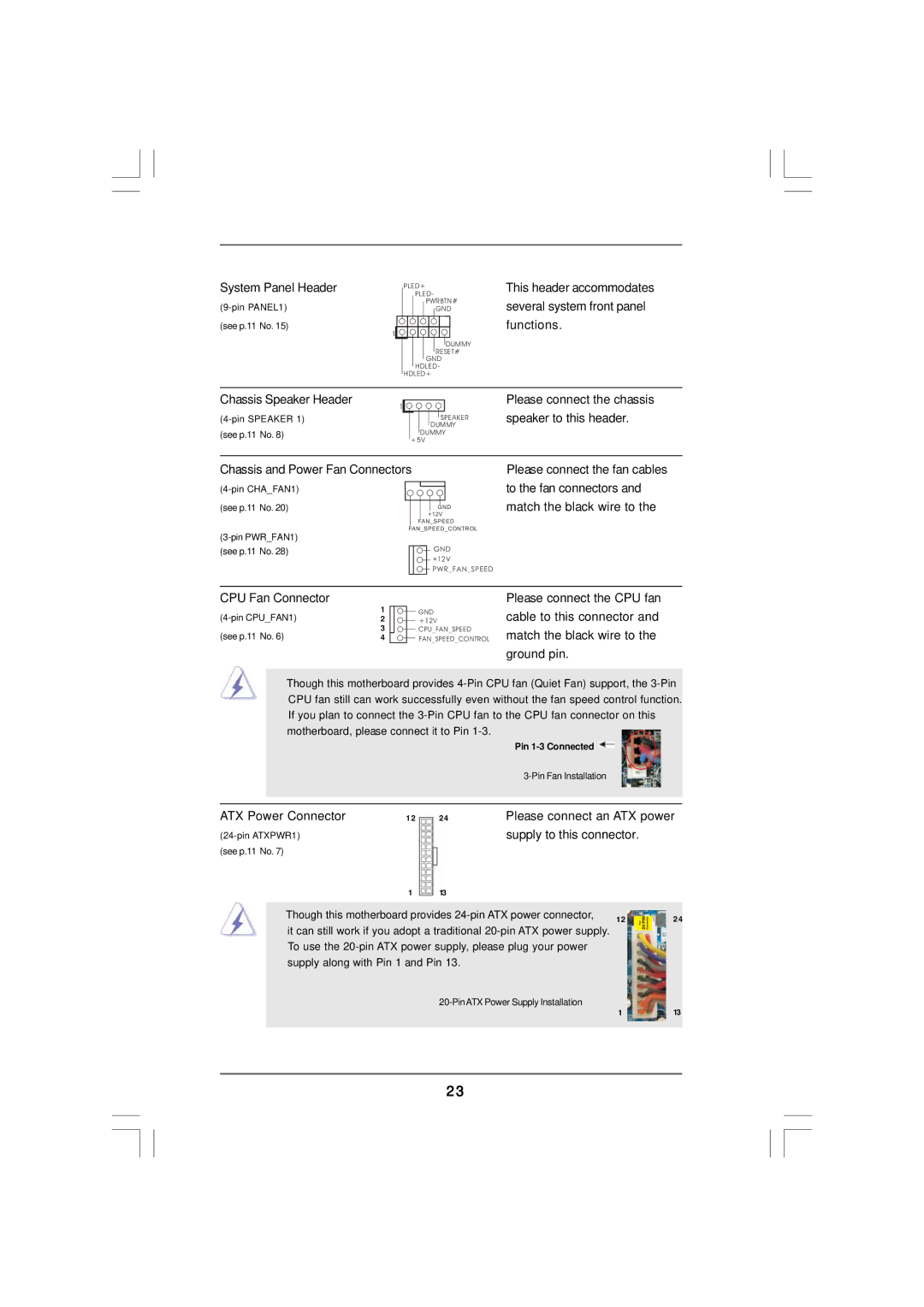
System Panel Header
(see p.11 No. 15)
1
PLED+
PLED-
PWRBTN#
GND
DUMMY RESET#
GND HDLED-
HDLED+
This header accommodates several system front panel functions.
Chassis Speaker Header
1
(see p.11 No. 8)
SPEAKER DUMMY
DUMMY +5V
Please connect the chassis speaker to this header.
Chassis and Power Fan Connectors
| |
(see p.11 No. 20) | GND |
| +12V |
| FAN_SPEED |
FAN_SPEED_CONTROL | |
| |
(see p.11 No. 28) | GND |
| +12V |
| PWR_FAN_SPEED |
Please connect the fan cables to the fan connectors and match the black wire to the
CPU Fan Connector
1 | GND | |
2 | +12V | |
(see p.11 No. 6) | 3 | CPU_FAN_SPEED |
4 | FAN_SPEED_CONTROL |
Please connect the CPU fan cable to this connector and match the black wire to the ground pin.
Though this motherboard provides
|
|
|
| Pin |
|
|
|
|
|
|
|
|
|
| |
|
|
|
|
|
| ||
ATX Power Connector | 12 | 24 | Please connect an ATX power | ||||
|
| supply to this connector. |
| ||||
(see p.11 No. 7) |
|
|
|
|
|
| |
|
| 1 | 13 |
|
|
|
|
|
|
|
|
| |||
| Though this motherboard provides | 12 |
| 24 | |||
|
| ||||||
| it can still work if you adopt a traditional |
| |||||
|
|
|
| ||||
| To use the |
|
|
| |||
| supply along with Pin 1 and Pin 13. |
|
|
|
| ||
|
|
| 1 |
| 13 | ||
|
|
|
|
|
| ||
|
|
|
|
|
|
|
|
23