Copyright Notice
Disclaimer
English
Motherboard Layout
LAN Port LED Indications
Table for Audio Output Connection
Activity/Link LED
English
Introduction
Package Contents
English Specifications
Connector
Smart Switch
USB
Unique Feature
Bios Feature
Support CD
Hardware
English
English
English
Pre-installation Precautions
Installation
Installation of CPU Fan and Heatsink
CPU Installation
Dual Channel Memory Configurations
English Installation of Memory Modules Dimm
Installing a Dimm
Installing an expansion card
English Expansion Slots PCI and PCI Express Slots
Pcie Slots
Requirements
Slitm and Quad Slitm Operation Guide
For Windows XP / XP 64-bit OS For Slitm mode only
Driver Installation and Setup
Double-click Nvidia Settings icon on your Windows taskbar
ASRock SLIBridge2S Card
Select Control Panel tab
Select Nvidia Control Panel tab
English
CrossFire Bridge
Installing Three CrossFireXTM-Ready Graphics Cards
CrossFireTM Bridge
For Windows XP OS
Install the required drivers to your system
For Windows 7 / VistaTM OS
ATI Catalyst Control Center
\ Surround Display Information
Surround Display Feature
Jumper
Jumpers Setup
Description
Clear Cmos Jumper
Onboard Headers and Connectors
Optional wireless transmitting
Serial ATA3 Connectors
USB 2.0 Headers
One USB 3.0 header on this
To receive stereo audio input
Internal Audio Connectors This connector allows you
From sound sources such as
CD-ROM, DVD-ROM, TV
Power LED to this header to
Power LED Header Please connect the chassis
Indicate system power status
Power off
Cable to the connector
CPU Fan Connectors
Match the black wire to Ground pin
ATX Power Connector Please connect an ATX power
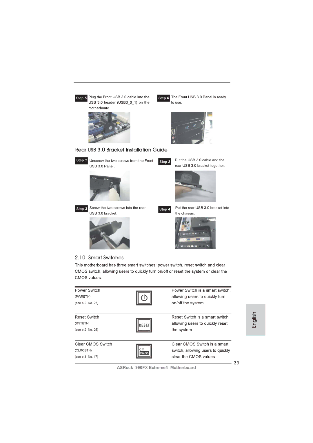
Front USB 3.0 Panel Installation Guide
Smart Switches
Rear USB 3.0 Bracket Installation Guide
Status Code Description
English 11 Dr. Debug
English
English
English
Installing Windows XP / XP 64-bit Without RAID Functions
English Driver Installation Guide
\ RAID Installation Guide
Install Windows XP / XP 64-bit OS on your system
Untied Overclocking Technology
Bios Information
Deutsch
Kartoninhalt
Spezifikationen
An der
Anschlüsse
Rückseite
USB3.0
Support-CD
Schnellschalter
Einzigartige
Eigenschaft Siehe Vorsicht
Unterstützt Microsoft Windows 7 / 7 64-Bit / Vista TM
Betriebssysteme
Vista TM 64-Bit / XP / XP 64-Bit
Zertifizierungen
Deutsch
Deutsch
Sicherheitshinweise vor der Montage
Schritt Schritt 2 / Schritt
Installation des CPU-Lüfters und des Kühlkörpers
Deutsch Installation der Speichermodule Dimm
Dual-Kanal-Speicherkonfigurationen
Blau Weiß Bestückt
Einsetzen eines DIMM-Moduls
Deutsch Erweiterungssteckplätze PCI- und PCI Express-Slots
Einbau einer Erweiterungskarte
PCI Express-Slots
SLITM- und Quad SLITM-Bedienungsanleitung
Einstellung der Jumper
JumperEinstellun
Cmos löschen
Integrierte Header und Anschlüsse
USB 2.0-Header
Seriell-ATA3-Anschlüsse
Ports am E/A-Panel
Befindet sich ein USB
Diese ermöglichen Ihnen
Stereo-Signalquellen, wie z. B
CD-ROM, DVD-ROM, TV-Tuner
Oder MPEG-Karten mit Ihrem
Schließen Sie den
Gehäuselautsprecher-Header
Gehäuselautsprecher an
Diesen Header an
ATX-Netz-Header Verbinden Sie die ATX
Pins 1-3 anschließen
Stromversorgung mit diesem
Header
ATX 12V Anschluss
Anschluss die ATX
Stromversorgung an
Installationsanleitung zum USB 3.0-Blech an der Rückwand
Installationsanleitung der USB 3.0-Frontblende
Schnellschalter
Debug-LED
Treiberinstallation
Deutsch
BIOS-Information
Contenu du paquet
Français
Spécifications
Connecteurs
Panneau arrière
Rapide
Interrupteur
CD d’assistance
Caractéristique
Monitoring de la tension +12V, +5V, +3.3V, Vcore
Commande de ventilateur CPU/boîtier à plusieurs vitesses
Microsoft Windows 7 / 7 64-bit / Vista TM / Vista TM 64-bit
XP / XP 64-bit
Français
Français
Précautions à observer avant l’installation
Installation du ventilateur et du dissipateur
Français Installation du CPU
Installation des modules m émoire Dimm
Configurations de Mémoire à Canal Double
Slot Bleu Slot Blanc Occupé
Installation d’un module Dimm
Installation d’une carte d’extension
Slot d’extension Slots PCI et Slots PCI Express
Slots Pcie
Mode d’emploi pour Slitm et Quad Slitm
Réglage des cavaliers
Le cavalier Description
Effacer la Cmos
Français En-têtes et Connecteurs sur Carte
En-tête USB
Cordon d’alimentation Série ATA Sata
USB 3.0 par défaut sur le
USB 3.0 sur la carte mère
Infrarouge optionnel de
En-tête du module infrarouge Cet en-tête supporte un module
Transfert et de réception sans
Connecteurs audio internes Ils vous permettent de gérer
Haut-parleur de châssis sur
En-tête du haut-parleur Veuillez connecter le De châssis
Cet en-tête
LED di accensione Collegare il LED di accensione
Connecteur du ventilateur
Connecteur pour châssis et ventilateur
De l’UC
Ventilateur d’UC sur ce
12V sur ce connecteur
Le Guide dinstallation du Support arrière USB
Le Guide d’installation du panneau USB 3.0 frontal
Guide d’installation des pilotes
Interrupteur rapides
LED de débogage
\ RAID Installation Guide Guide d’installation RAID
Installation de Windows XP / XP 64-bit sans fonctions RAID
Français
Informations sur le Bios Informations sur le CD de support
Contenuto della confezione
Italiano
Scheda madre ASRock 990FX Extreme4
Specifiche Italiano
Pannello
Supporta PXE
Posteriore
Connettori
Rapido
Interruttore
CD di
Supporto
Attenzione
Italiano
Italiano
Precauzioni preinstallazione
Installazione
Installazione della ventolina e del dispersore di calore
Installazione del processore
100
Italiano Installazione dei moduli di memoria Dimm
Configurazioni Dual Channel Memory
Popolato
101
Installare una Dimm
Installare una scheda di espansione
Italiano Slot di espansione Slot PCI ed Slot PCI Express
102
103
Guida operativa per Slitm e Quad Slitm
Resettare la Cmos
Setup dei Jumpers
104
Jumper Settaggio del Jumper
Collettori e Connettori su Scheda
106
107
Reset interruttore di ripristino
Collettore pannello di sistema
Diverse funzioni di sistema
Collettore casse telaio Collegare le casse del telaio a
108
Questo collettore
Collettori Chassis ed alimentazione ventola
109
110
Guida all’installazione del pannello frontale USB
Guida di installazione del supporto USB 3.0 posteriore
111
112
Interruttori rapidi
Installazione di Windows XP / XP 64 bit senza funzioni RAID
Guida installazione del driver
LED di debug
113
114
115
Español
Contenido de la caja
116
117
Especificación
Entrada/Salida
118
De Panel
Trasero
119
Certificaciones
120
121
122
123
Precaución de Pre-instalación
Instalación del Ventilador y el Radiador de la CPU
Español Instalación de Procesador
124
Paso 4. Encierre el zócalo bajando la palanca
Instalación de Memoria
125
Configuraciones de Memoria de Doble Canal
126
Español Instalación de una Dimm
Instalación de Tarjetas de Expansión
Ranuras de Expansión ranuras PCI y ranuras PCI Express
127
Ranura PCI Express
128
Manual de uso de Slitm y Quad Slitm
Jumper Setting
Setup de Jumpers
129
Limpiar Cmos
Cabezales y Conectores en Placas
Español
130
131
Cabezal de panel de sistema
132
Sistema
Pwrbtn interruptor de alimentación
133
134
Conector de ATX 12V power
Conector del ventilador de la CPU
Cabezal de alimentación ATX Conecte la fuente de
135
Guía de instalación del Panel frontal USB
Guía de instalación del soporte USB 3.0 posterior
136
137
Conmutadores rápidos
11 Guía de instalación del controlador
Español Indicador LED de depuración
Instalación de Windows XP / XP 64 bits sin Funciones
138
139
140
Bios Información Información de Software Support CD
Русский
Комплектность
141
80-жильный ленточный IDE-кабель Ultra ATA 66/100/133
142
Спецификации
Колодки и
USB
Плате
Переключение
144
Осторожно
145
146
147
148
Меры предосторожности
Установка процессора
Установка вентилятора и радиатора ЦП
149
150
Русский Установка модулей памяти Dimm
Конфигурации двухканальной памяти
Синий Белый Заполнено
151
Установка модуля Dimm
Русский Гнезда расширения PCI и PCI Express
Установка карты расширения
152
153
Руководство по эксплуатации Slitm и Quad Slitm
Установка перемычек
154
Перемычка Установка Описание
Колодки и разъемы на плате
155
Разъем дисковода гибких дисков
Разъемы Serial ATA3
156
157
158
Reset кнопка сброса
Pwrbtn кнопка питания
Pled индикатор питания системы
Контакты 1-3 подключены
159
Наряду с Булавкой 1 и Прикрепите
160
Руководство по установке передней панели USB
Руководство по установке кронштейна заднего разъема USB
161
162
Быстрое переключение
10 Режим отладки
11 Указания по установке драйверов
163
ШАГ 1. Установите параметры Uefi
164
ШАГ 2. Установите на свою систему Windows XP / XP 64-bit
SATA37 и SATA38
165
Информация о Bios
Türkçe
Paket İçindekiler
166
167
Özellikler
Konektör
168
169
170
Dİkkat
171
172
Kurulum Öncesi Önlemler
CPUnun Takılması
CPU Fanı ve Isı Emicisinin Takılması
173
174
Bellek Modüllerinin Dimm Takılması
Çift Kanallı Bellek Yapılandırmaları
Beyaz Yuva Mavi Yuva
175
Bir Dimm takma
Genişletme Yuvaları PCI ve PCI Express Yuvaları
Genişletme kartı takma
176
177
Slitm ve Quad Slitm Çalıştırma Kılavuzu
178
Jumperların Ayarı
Jumper Ayar
CMOS’u temizleme
179
Yerleşik Fişler ve Konektörler
180
Ön Panel Ses Fişi
181
Sistem Paneli Fişi
Işlevini barındırır
182
ATX Güç Konektörü Lütfen bir ATX güç kaynağını
183
Bu konektöre bağlayın
Ieee 1394 Fişi
184
Ön USB 3.0 Panelinin Kurulum Kılavuzu
Arka USB 3.0 Braketinin Kurulum Kılavuzu
Akıllı Anahtarlar
185
11 Sürücü Yükleme Kılavuzu
10 Dr. Debug
Windows XP / XP 64-biti RAID İşlevleri Olmadan Yükleme
186
187
188
Bios Bilgileri Yazılım Destek CD’si bilgileri
189
차폐 1 개 USB 3.0 전면 패널 1 개 HDD 나사 4 개
후면 USB 3.0 브래킷 1개 ASRock SLI 브릿지 2S 카드 1 개
190
191
192
193
194
이것은 ATX 폼 팩터 30.5x24.4 cm, 12.0x9.6 in. 머더보드입니다
195
196
CPU 설치
197
메모리 모듈 설치하기
198
메모리의 설치
PCIE5 Pcie x16 슬롯 파란색 는 PCI Express x4 레인폭 그래 픽
199
200
Slitm 및 Quad Slitm 사용 설명서
Cmos 초기화
201
202
USB 2.0 헤더
203
USB 3.0 헤더
콘넥터는 CD-ROM, DVD
콘넥터는 오디오 장치를 편리하게 조절하고 연결할 수 있는 전면 오디오 인터페이스 입니다
204
섀시 및 전원 팬 커넥터
205
206
207
208
전면 USB 3.0 패널의 설치 안내서
209
빠른 스위치
210
\ RAID Installation Guide
211
RAID 기능이 지원되지 않는 Windows XP / XP 64 비트
212
\ BIN \ ASSETUP.EXE, D 는 CD-ROM 드라이브
日本語
パッケージ内容
213
シリアル l ATA Sata HDD 用電源変換ケーブル(オプション)
214
215
216
217
218
219
220
インストレーションを行う前の注意事項
CPU インストレーション
CPU ファンとヒートシンクのインストール
221
222
日本語 メモリーモジュール Dimm 取り付け
223
日本語 拡張スロット(PCI スロット、PCI Express スロット)
拡張カードの装着
224
225
Slitm および Quad Slitm 操作ガイド
ジャンパ設定
日本語 オンボードのヘッダとコネクタ類
226
227
228
229
シャーシおよび電源ファンコネクタ
230
ATX パワーコネクタ ATX 電源コネクタを接続します。
231
日本語 前面USB 3.0パネルの取り付けガイド
背面USB 3.0ブラケットの取り付けガイド
232
10 デバッグ LED
クイックスイッヱ
11 ドライバインストールガイド
233
ビットをインストールする
トをインストールする
RAID 機能を搭載しない Windows XP / XP 64-bit
トールする
このマザーボードは Microsoft Windows 7 / 7 64-bit / VistaTM / VistaTM
235
236
簡體中文
237
主板規格
和熱插拔功能
238
支持 CPU 無級頻率調控(見警告 12)
239
若您想要更快速、更自由地為您的蘋果設備 , 如 iPhone/iPad/iPod touch
240
10. 華擎 XFast USB 可以提升 USB 存儲設備性能。性能可能因設備特性不 同而存在差異。
241
242
安全防范
243
安裝 CPU 風扇和散熱片
244
內存安裝
245
安裝步驟:
246
擴展插槽 PCI 和 PCI Express 插槽
247
操作指南
板載接頭和接口
跳線設置
數據線
249
前置音頻面板接頭 可以方便連接音頻設備。
250
板功能。
251
CPU 風扇接頭
252
253
前部USB 3.0面板安裝指南
后部USB 3.0面板安裝指南
簡體中文 快速開關
254
10 調試 LED
11 驅動程序安裝指南
255
步驟 1 設置 UEFI。
256
257
支持光盤信息
258
電子信息產品污染控制標示
259
四條 Serial Atasata 數據線 選配
一個後USB 3.0托架 一張華擎 SLIBridge2S 卡
260
261
262
若您想要更快速、更自由地為您的蘋果設備 , 如 iPhone/iPad/iPod touch
263
264
265
主機板安裝
266
CPU 安裝
No.10)或者在雙通道 B 安裝同樣的 DDR3 記憶體(DDR3A2 和 DDR3B2;白色插
267
268
安裝步驟:
269
擴充插槽 PCI 和 PCI Express 插槽
Slitm 和 Quad Slitm 操作指南
CrossFireXTM,3-Way CrossFireXTM 和 Quad CrossFireXTM
270
跳線設置
271
清除 Cmos
272
273
前置音效接頭 可以方便連接音效設備。
274
CPU 風扇接頭
275
ATX 電源接頭
276
ATX 12V 電源接口
Ieee 1394 接口
277
前USB 3.0面板安裝指南
Cmos 中的數據。
278
13.1 在不帶 RAID 功能的系統上安裝 Windows XP / XP 64 位元
Using SATA3 HDDs without NCQ and Hot Plug functions
279
如果您只想在不帶 RAID 功能的 SATA3 硬碟上安裝 Windows 7 / 7 64 位元 / VistaTM
使用不帶 NCQ 和熱插拔功能的 SATA3 硬碟 步驟 1 設置 UEFI。
280
281
Installing OS on a HDD Larger Than 2TB