RESET (Reset Switch):
Connect to the reset switch on the chassis front panel. Press the reset switch to restart the computer if the computer freezes and fails to per- form a normal restart.
PLED (System Power LED):
Connect to the power status indicator on the chassis front panel. The LED is on when the system is operating. The LED keeps blinking when the
HDLED (Hard Drive Activity LED):
Connect to the hard drive activity LED on the chassis front panel. The LED is on when the hard drive is reading or writing data.
The front panel design may differ by chassis. A front panel module mainly consists of power switch, reset switch, power LED, hard drive activity LED, speaker and etc. When connecting your chassis front panel module to this header, make sure the wire assignments and the pin
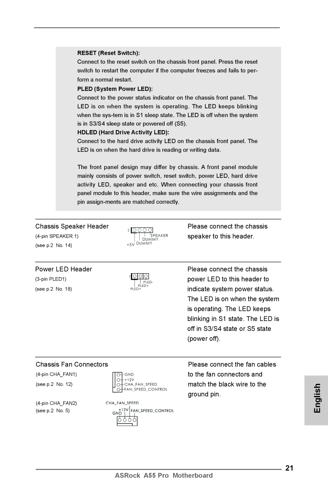
Chassis Speaker Header | Please connect the chassis |
speaker to this header. | |
(see p.2 No. 14) |
|
Power LED Header
1 |
|
|
|
|
|
| |
|
|
|
|
|
| PLED- | |
(see p.2 No. 18) |
|
|
| PLED+ | |||
PLED+ | |||||||
Please connect the chassis power LED to this header to indicate system power status. The LED is on when the system is operating. The LED keeps blinking in S1 state. The LED is off in S3/S4 state or S5 state (power off).
Chassis Fan Connectors
GND | |
(see p.2 No. 12) | +12V |
CHA_FAN_SPEED | |
| FAN_SPEED_CONTROL |
(see p.2 No. 5)
Please connect the fan cables to the fan connectors and match the black wire to the ground pin.
English
21
ASRock A55 Pro Motherboard