Copyright Notice
Disclaimer
English
Published May Copyright2013 ASRock INC. All rights reserved
Motherboard Layout
LAN Port LED Indications
Off No Link Blinking
Link
Activity/Link LED
Package Contents
Introduction
Specifications
Connector
Bios Feature
Unique Feature
Support CD
CPU Quiet Fan
CPU/Chassis Fan Multi-Speed Control
Voltage Monitoring +12V, +5V, +3.3V, Vcore
SP3 / XP 64-bit compliant see Caution
English
English
Installation
Pre-installation Precautions
CPU Installation
Installation of CPU Fan and Heatsink English
English Installation of Memory Modules Dimm
Installing a Dimm
Installing an expansion card
Expansion Slots PCI and PCI Express Slots
AMD Dual Graphics Operation Guide
Enjoy the benefit of AMD Dual Graphics
What does an AMD Dual Graphics system include?
AMD Vision Engine Control Center
Dual Monitor and Surround Display Features
Dual Monitor Feature
Sub port
Surround Display Feature
For Windows XP / XP 64-bit OS
What is HDCP?
For Windows 7 / 7 64-bit / VistaTM / VistaTM 64-bit OS
Hdcp Function
ASRock Smart Remote Installation Guide
Install Multi-Angle CIR Receiver to the front USB port
Make sure the option CIR Controller is setting at Enabled
Advanced Super IO Configuration CIR Controller Enabled
CIR sensors in different angles
Jumpers Setup
Jumper
Description
Clear Cmos Jumper
Onboard Headers and Connectors
Optional wireless transmitting
Infrared Module Header This header supports an
Receiving infrared module
Consumer Infrared Module Header This header can be used to
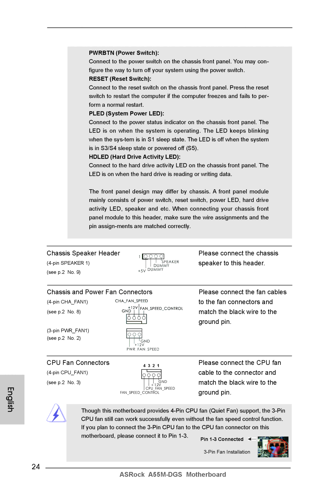
To the fan connectors
Match the black wire to
Chassis Speaker Header Please connect the chassis
Speaker to this header
Driver Installation Guide
ATX Power Connector
\ RAID Installation Guide
Installing Windows XP / XP 64-bit Without RAID Functions
Install Windows XP / XP 64-bit OS on your system
Bios Information
Kartoninhalt
Deutsch
Spezifikationen
Anschlüsse
An der
Rückseite
Support-CD
Zertifizierungen
Warnung
Vorsicht
Deutsch
Deutsch
Einstellung der Jumper
Jumper Einstellun Beschreibung
Cmos löschen
Nur gelöscht werden, wenn die CMOS-Batterie entfernt wird
Anschlüsse
Anschluss Beschreibung
Infrarot-Modul-Header Dieser Header unterstützt ein
Optionales, drahtloses Sende
Und Empfangs-Infrarotmodul
Consumer Infrared-Modul-Header Dieser Header kann zum
System Panel-Header
Mehrere Funktion der
Systemvorderseite
Gehäuselautsprecher-Header Schließen Sie den
CPU-Lüfteranschluss
Verbinden Sie die ATX
Stromversorgung mit diesem
Header
COM-Anschluss-Header Dieser COM-Anschluss
Header wird verwendet, um
Unterstützen
Contenu du paquet
Français
Spécifications
Panneau arrière
Connecteurs
Caractéristique
Caractéristique Voir Attention Unique
Surveillance
Système
Français
Français
Français
Réglage des cavaliers
Le cavalier Description
Effacer la Cmos
En-têtes et Connecteurs sur Carte
En-tête du module infrarouge Cet en-tête supporte un module
Infrarouge optionnel de
Transfert et de réception sans
Fil
En-tête du haut-parleur Veuillez connecter le De châssis
Cet en-tête
Connecteur pour châssis et ventilateur
Connecteur du ventilateur
De l’UC Ventilateur d’UC sur ce
Connecteur et brancher le fil
Noir sur la broche de terre
Informations sur le Bios Informations sur le CD de support
Italiano
Contenuto della confezione
Specifiche
Pannello
Posteriore I/O
Connettori
CD di
Monitoraggio
Compatibi
Lità SO
Certificazioni
Attenzione
Italiano
Italiano
Setup dei Jumpers
Resettare la Cmos
Jumper Settaggio del Jumper
Collettori e Connettori su Scheda
Collettore modulo infrarossi Questo collettore supporta
Moduli ad infrarossi optional
Per la trasmissione e la
Ricezione senza fili
Collettore pannello di sistema
Diverse funzioni di sistema
Collettore casse telaio
Questo collettore
Corrispondenti connettori
Facendo combaciare il cavo
Nero col pin di terra
Combaciare il filo nero al pin
Collettore porta COM Questo collettore porta COM è
Utilizzato per supportare il
Modulo porta COM
Contenido de la caja
Español
Español Especificación
Entrada/Salida
De Panel
Trasero
Conectores
Monitor Hardware
Certificaciones
Atención
Español
Español
Setup de Jumpers
Jumper Setting
Limpiar Cmos
Cabezales y Conectores en Placas
Wireless opcional
Cabezal de Módulo Infrarrojos Este cabezal soporta un
Módulo infrarrojos de
Transmisión y recepción
Cabezal del altavoz del chasis
Su cabezal
Conectores de ventilador de chasis y alimentación
Cabezal de alimentación ATX Conecte la fuente de
Cabezal del puerto COM Este cabezal del puerto COM
Se utiliza para admitir un
Módulo de puerto COM
Введение
Платформа
Процессор
Набор микросхем
Память
Колодки и
Плате
Компактдиск
Поддержки
Операцион
См. ОСТОРОЖНО, пункт Ные
Системы
Сертификаты
Осторожно
Русский
Русский
Установка перемычек
Перемычка Установка Описание
Колодки и разъемы на плате
Колодка инфракрасного модуля Данная колодка позволяет
Reset кнопка сброса
Pwrbtn кнопка питания
Pled индикатор питания системы
Hdled индикатор активности жесткого диска
Контакты 1-3 подключены
Информация о Bios
Giriş
Türkçe
Yonga seti
Bellek
Genişletme
Yuvası
Bios Özelliği
Konektör
Destek CD’si
Benzersiz
Sertifikalar
Bkz. Dİkkat
Türkçe
Türkçe
Jumper Ayar
CMOS’u temizleme
100
101
102
103
Bios Bilgileri Yazılım Destek CD’si bilgileri
104
105
차폐 1 개
106
107
108
CPU 저소음 팬
전압 감시 기능 +12V,+5V,+3.3V,Vcore
마이크로 소프트 Windows 7/7 64 비트 /Vista TM
109
110
111
Cmos 초기화
112
개의 시리얼 ATA2 SATA2 커넥터는 내부 저장
USB 2.0 헤더
113
콘넥터는 오디오 장치를 편리하게 조절하고 연결할 수 있는 전면 오디오 인터페이스 입니다
114
115
ATX 12V 파워 콘넥터 ATX 12V 플러그가 달린
\ BIN \ ASSETUP.EXE, D 는 CD-ROM 드라이브
116
117
I/O パネルシールド
118
119
120
121
ASRock Instant Flash は、Flash ROM(フラッシュ ROM)に組み込ま
ASRock XFast RAM は、ASRock Extreme Tuning Utility Axtu
122
123
ジャンパ設定
124
オンボードのヘッダとコネクタ類
125
126
コンシューマー赤外線モジュールヘッダー このヘッダーは、リモコン受光部
127
シャーシに付いている電源スイッチ、リセットスイッチ、システムステータ
128
CPU ファンコネクタ
129
このマザーボードは Microsoft Windows 7 / 7 64-bit / VistaTM / VistaTM
主板簡介
130
131
132
133
電壓範圍:+12V, +5V, +3.3V, 核心電壓
Microsoft Windows 7/7 64 位元 /Vista TM/Vista TM 64 位元
XP SP3/XP 64 位元适用于此主板(見警告 12 )
134
12、Microsoft Windows XP / XP 64-bit 系統不支持華擎 XFast RAM。
135
清除 Cmos
136
137
可以方便連接音頻設備。
138
CPU 風扇接頭
139
ATX 電源接頭
ATX 12V 接頭
140
本主板支持各種微軟視窗操作系統:Microsoft Windows 7/7 64 位元 /VistaTM
電子信息產品污染控制標示
141
142
Micro ATX 規格 8.8 英吋 x 6.8 英吋 , 22.4 公分 x 17.3 公分
143
144
145
支援 ErP/EuP 需要同時使用支援 ErP/EuP 的電源供應器 (見警告 13)
146
12、Microsoft Windows XP / XP 64-bit 系統不支援華擎 XFast RAM。
147
148
SATA2 接口支援 Sata 數據
USB 2.0 擴充接頭
USB 2.0 接口之外,這款
149
可以方便連接音效設備。
150
151
ATX 12V 電源接口
支援光碟訊息
152
Isi Paket
153
Spesifikasi
154
Ciri-ciri Bios
155
Fitur Unik
156
Penjaga
Sertifikasi
Installing OS on a HDD Larger Than 2TB in Ahci Mode
157
158
Drv4E CtrlB5 Langeng
Key in dh Drv number, for example key in dh 4E
159
Choose Usable Physical Drive List to select Raid HDD
160
161
Windows VistaTM 64-bit
162
163
Windows 7 64-bit
Finish