Copyright Notice
Infringe
Motherboard Layout
ATXPWR1
No. Description
Panel
Off No Link Blinking Data Activity
Speed LED Status Description
Package Contents
Introduction
Specifications
Audio
Rear Panel
Storage
Connector
Feature
Support
English
Unique Features
ASRock A-Tuning
ASRock System Browser
ASRock Interactive Uefi
Installation
Installing the CPU
B85M-ITX
English
Installing the CPU Fan and Heatsink
Installing Memory Modules Dimm
English
Expansion Slots PCI and PCI Express Slots
There is 1 PCI Express slot on this motherboard
See p.1, No
Jumpers Setup
Default
Onboard Headers and Connectors
System Panel Header Pin PANEL1 See p.1, No
Pin HDAUDIO1 See p.1, No
USB 2.0 Headers Pin USB1011 See p.1, No
Header can support two ports
Chassis Fan Connector Pin CHAFAN1 See p.1, No
Pin CPUFAN1 See p.1, No
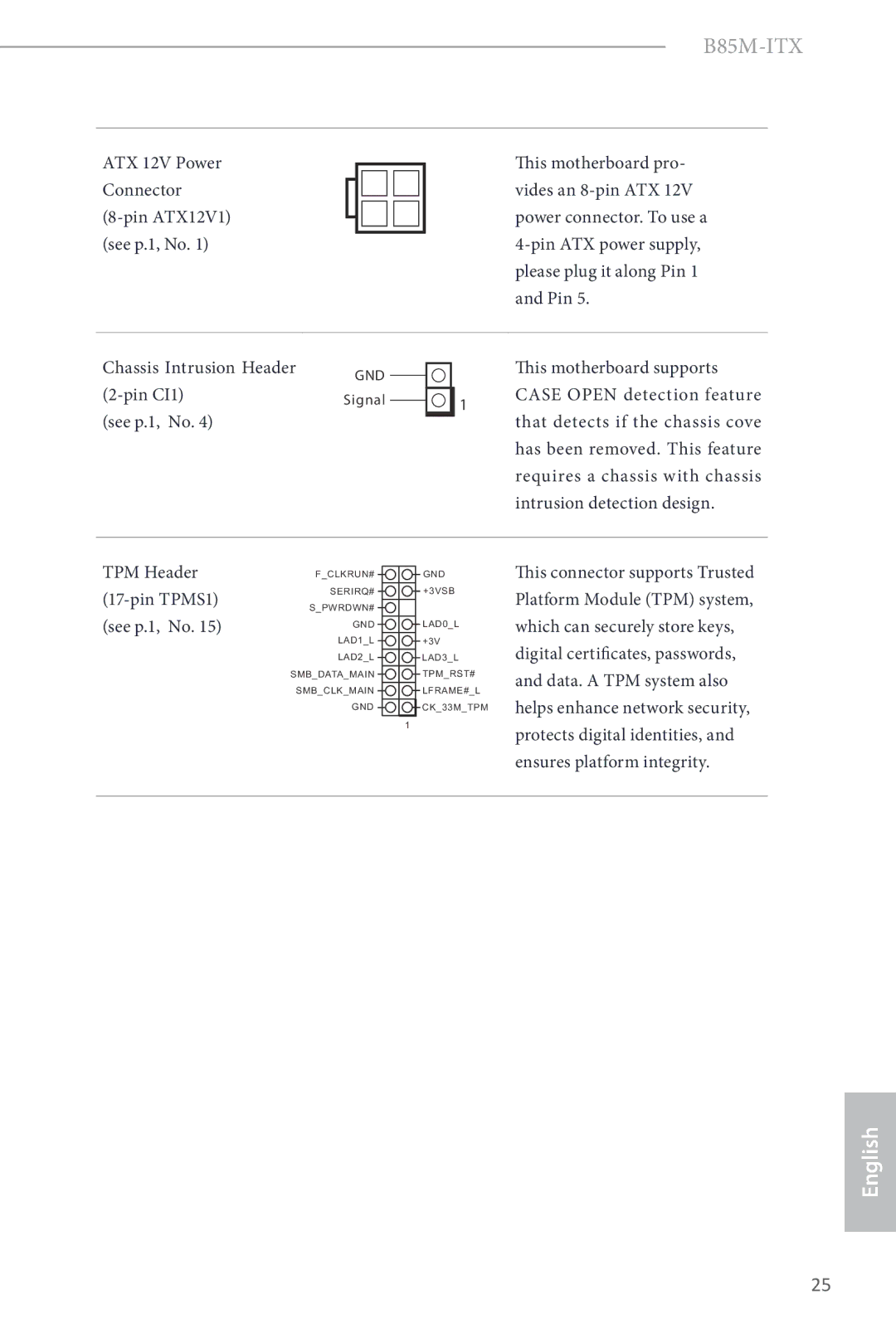
Pin CI1
Einleitung
Lieferumfang
Prozessor
Technische Daten
Plattform
Chipsatz
Rückblende
Anschluss
BIOS-Funktion
Speicher
Support-CD
Deutsch
Standard Cmos löschen
Jumpereinstellung
CMOS-löschen-Jumper
Siehe S , Nr
Integrierte Stiftleisten und Anschlüsse
Audiostiftleiste Frontblende
USB 2.0-Stiftleisten Polig, USB1011 Siehe S , Nr
USB 3.0-Stiftleisten Polig, USB356 Siehe S , Nr
Lüfterkabel mit dem
Gehäuselüfteranschluss
Polig, CHAFAN1
Lüfteranschluss der
Dieses Motherboard
ATX-12-V-Netzanschluss Polig, ATX12V1 Siehe S , Nr
Gehäuseeingriff
Stiftleiste2-polig, CI1
Contenu de l’emballage
Spécifications
Du panneau
Réseau
Connectique
Arrière
Caractéris
Tiques du Bios
Stockage
CD inclus
Certifications FCC, CE, Whql
ErP/EuP Ready alimentation ErP/EuP ready requise
Par défaut Fonction Clear Cmos
Configuration des cavaliers Jumpers
Cavalier Clear Cmos
Voir p.1, No
Embases et connecteurs de la carte mère
Embase du panneau sys- tème
De 6,0 Go/s
Ces quatre connecteurs
SATA30
ATX
Châssis CI1 à 2 broches
Connecteur d’alimentation ATX
Embase d’intrusion
Introduzione
Contenuto della confezione
Memoria
Specifiche
Piattaforma
Slot di
Pannello
Posteriore
Caratteristi
Che del Bios
Connettore
CD di
Certificazioni FCC, CE, Whql
ErP/EuP Ready è necessaria alimentazione ErP/EuP ready
Impostazione jumper
Vedere pag , n
Header e connettori sulla scheda
Header sul pannello del sistema
Vedere pag.1, n Gb/s SATA33
Connettori Serial ATA3
SATA30 SATA3 supportano cavi Vedere pag.1, n
Questo header serve a
Dello chassis
Connettore della ventola
Collegare il cavo della
CHAFAN1 a 4 pin
Header di intrusione nello Chassis CI1 a 2 pinGND
Di garantire lintegrità della piattaforma
Introducción
Contenido del paquete
Especificaciones
Miento
Panel trasero
Almacena
Características
Del Bios
Conectores
CD de soporte
Certificaciones FCC, CE, Whql
Predeterminado Borrado de Cmos
Instalación de los puentes
Puente de borrado de
Consulte la pág.1, N.º
Conectores y cabezales incorporados
Cabezal del panel del siste- ma
SATA32 Con una velocidad de
Conectores Serie ATA3
SATA31 Para dispositivos de
SATA33 Hasta 6,0 Gb/s
Conector de alimentación
Cabezal de intrusión de Chasis CI1 de 2 pines
Cabezal TPM TPMS1 de 17 pines consulte la pág.1, N.º
Введение
Комплект поставки
Спецификация
Вывода
Аудио
Порты ввода
На задней
Разъемы
Диск с ПО
Сертификация FCC, CE, Whql
Установка перемычек
Колодки и разъемы, расположенные на материнской плате
См. стр.1 Гб/с
Разъемы Serial ATA3
Эти четыре
Корпуса
Разъем вентилятора
Предназначен для
Подключения кабеля
Колодка для датчика
Вскрытия корпусаSignal 1 2-контактная, CI1 См. стр
Разъем питания АТХ 12 В 8-контактный, ATX12V1 См. стр
Обеспечивает целостность платформы
Introdução
Conteúdo da embalagem
Ranhuras de
Especificações
Memória
Expansão Gráficos
Traseiro
Áudio
Do painel
Armazena
Funcionalida
Des da Bios
Conector
CD de suporte
Português
Predefinição Limpar Cmos
Configuração dos jumpers
Jumper para limpar o
Consultar p.1, N.º
Terminais e conectores integrados
Pwrbtn Botão de alimentação
SATA32 Com uma velocidade de Consultar p.1, Nº
Conectores ATA3 de série
SATA3 suportam
SATA33 Até 6,0 Gb/s Consultar p.1, N.º
Conector da ventoinha do chassis
ATXPWR1 de 24 pinos Consultar p.1, N.º
ChassisCI1 de 2 pinos
Terminal TPM TPMS1 de 17 pinos consultar p.1, N.º
Giriş
Ambalaj İçeriği
Bellek
Özellikler
Yonga kümesi
Genişletme
Ses
Depolama
Destek CDsi
Bios Özelliği
Bağlayıcı
Donanımİzle
Belgeler
Bağlantı Teli Kurulumu
Kart Üzerindeki Bağlantı ve Konektörler
Bkz sf.1, No
Içindir
Veri aktarım hızı 6,0 Gb
Pin HDAUDIO1
Teli topraklama pinine
Kasa Fanı Konektörü
Lütfen fan kablosunu fan
Bağlayın
Bağlantısı
Pin CI1 Bkz. sf.1, No
포장 내용물
플랫폼
LED
Bios 기능
FCC, CE, Whql
100
점퍼 설정
항목 참조
온보드 헤더 및 커넥터
103
104
105
はじめに
I/O パネルシールド
PCI Express 3.0 x16 スロット
I3 / Xeon / Pentium / Celeron をサポート
DDR3 Dimm スロット
ピクセルシェーダー 5.0 、DirectX
Pcie x1 ギガビット LAN 10/100/1000 Mb/ 秒
Sub をサポート。最大解像度 1920x1200 @60Hz
DVI-D と Hdmi ポートで、HDCP 機能をサポート
ストレージ 4 x SATA3 6.0 Gb/ 秒コネクター、NCQ、AHCI、「ホットプラグ」
Bios 機能
110
ジャンパー設定
(p.1 、No 参照)
オンボードのヘッダーとコネクター
(p.1、No 参照)
パネルの 2 つの USB
(SATA30:
USB 2.0 ヘッダー
USB 2.0 ヘッダーは、2 つ
(4 ピン CHAFAN1)
(4 ピン CPUFAN1)
115
包装清单
支持 Intel Turbo Boost 2.0 技术
Mini-ITX 规格尺寸
Pentium / Celeron
支持 Intel Small Business Advantage
优质 Blu-ray 音频支持
支持 D-Sub,60Hz 时最大分辨率达
通过 DVI-D and Hdmi 端口支持 Hdcp 功能
支持 Qualcomm Atheros 网上安全唤醒技术
Bios 功能特点
120
跳线设置
板载接脚和接口
(9 针 PANEL1)
(SATA33
(SATA30
(SATA31
USB 2.0 接脚 (9 针 USB1011)
ATX 电源接口
(4 针 CHAFAN1)
CPU 风扇接口 (4 针 CPUFAN1)
(24 针 ATXPWR1)
(2 针 CI1 )
ATX 12V 电源接口
(8 针 ATX12V1 )
TPM 接脚 (17 针 TPMS1)
電子信息產品污染控制標示
包裝內容
支援 Intel Turbo Boost 2.0 技術
Mini-ITX 尺寸
Celeron (LGA1150 封裝)
支援 Intel Small Business Advantage
ESATA 接頭,支援 NCQ、AHCI 及「熱插拔」功能
支援最高達 1920x1200 @ 60Hz 解析度的 D-Sub
支援 Energy Efficient Ethernet 802.3az
ErP/EuP Ready(需具備 ErP/EuP ready 電源供應器)
Bios 功能
電壓監控:+12V、+5V、+3.3V、CPU Vcore 相容 Microsoft
131
跳線設定
板載排針及接頭
(9-pin PANEL1)
USB 2.0 排針
Serial ATA3 接頭 (SATA30 :
(SATA32
(9-pin USB1011 )
(4-pin CPUFAN1)
(4-pin CHAFAN1)
CPU 風扇接頭
ATX 電源接頭
Pin 5。
Pin ATX 12V 電
Pin ATX 電源供應
機殼防護排針(2-pin CI1)
Pendahuluan
Isi Kemasan
Slot Ekspansi
Spesifikasi
Memori
Grafis
Penyimpanan
Panel I/O
Belakang
Dukungan CD
Fitur Bios
Konektor
Perangkat
141
Lihat hal , No Default
Konfigurasi Jumper
Pwrbtn Switch Daya
Header dan Konektor Onboard
Header ini untuk
Konektor Serial ATA3
SATA32 Data hingga 6,0 Gb/s Lihat hal , No SATA33
Depan
Ke konektor kipas, lalu
Konektor Kipas Chassis
CHAFAN1 4-pin
Cocokkan kabel hitam
Intrusi Chassis CI1
Konektor Daya ATX 12V ATX12V1 8-pin Lihat hal , No
Header
Page
Page
Page
Page
Page
Page
Page
Page
Page
Page
Contact Information
EC-Declaration of Conformity