2.7 Onboard Headers and Connectors
Onboard headers and connectors are NOT jumpers. Do NOT place jumper caps over these headers and connectors. Placing jumper caps over the headers and connectors will cause permanent damage of the motherboard!
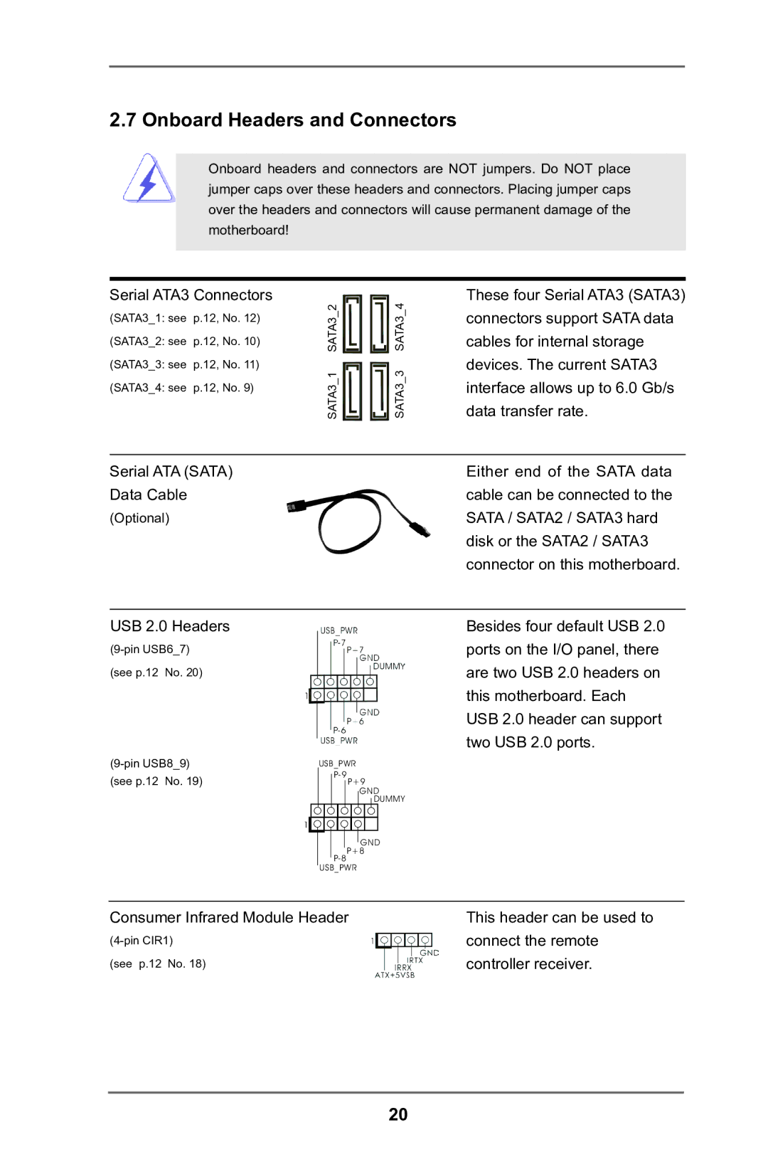
Serial ATA3 Connectors
(SATA3_1: see | p.12, No. 12) | SATA3_2 | SATA3_4 | |
(SATA3_2: see | p.12, No. 10) | |||
|
| |||
(SATA3_3: see | p.12, No. 11) | SATA3_1 | SATA3_3 | |
(SATA3_4: see | p.12, No. 9) | |||
|
|
Serial ATA (SATA)
Data Cable
(Optional)
USB 2.0 Headers
(see p.12 No. 20)
USB_PWR | |
(see p.12 No. 19) | |
P+9 | |
| GND |
| DUMMY |
| 1 |
| GND |
| P+8 |
| |
| USB_PWR |
Consumer Infrared Module Header
(see p.12 No. 18)
These four Serial ATA3 (SATA3) connectors support SATA data cables for internal storage devices. The current SATA3 interface allows up to 6.0 Gb/s data transfer rate.
Either end of the SATA data cable can be connected to the SATA / SATA2 / SATA3 hard disk or the SATA2 / SATA3 connector on this motherboard.
Besides four default USB 2.0 ports on the I/O panel, there are two USB 2.0 headers on this motherboard. Each USB 2.0 header can support two USB 2.0 ports.
This header can be used to connect the remote controller receiver.
20