2. Cabling
4202 E1 Uplink Module Connectors
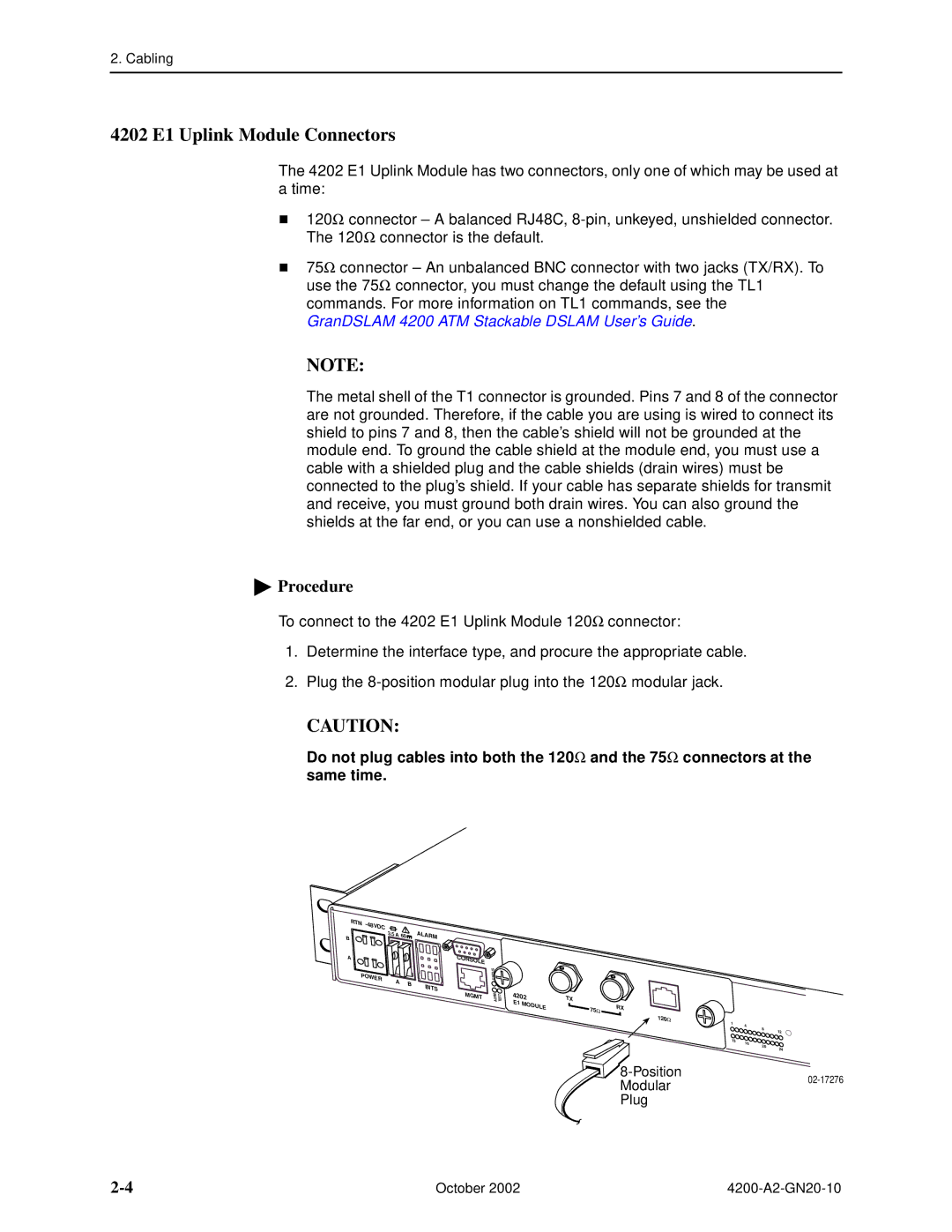
he 4202 E1 Uplink Module has two connectors, only one of which may be used at a time:
120Ω connector – A balanced RJ48C,
TThe 120Ω connector is the default.
75Ω connector – An unbalanced BNC connector with two jacks (TX/RX). To use the 75Ω connector, you must change the default using the TL1 commands. For more information on TL1 commands, see the GranDSLAM 4200 ATM Stackable DSLAM User’s Guide.
NOTE:
The metal shell of the T1 connector is grounded. Pins 7 and 8 of the connector are not grounded. Therefore, if the cable you are using is wired to connect its shield to pins 7 and 8, then the cable’s shield will not be grounded at the module end. To ground the cable shield at the module end, you must use a cable with a shielded plug and the cable shields (drain wires) must be connected to the plug’s shield. If your cable has separate shields for transmit and receive, you must ground both drain wires. You can also ground the shields at the far end, or you can use a nonshielded cable.
 Procedure
To connect to the 4202 E1 Uplink Module 120Ω connector:
1. Determine the interface type, and procure the appropriate cable.
2. Plug the
CAUTION:
Do not plug cables into both the 120Ω and the 75Ω connectors at the same time.
RTN - |
|
|
|
|
48VDC | 3.5 |
|
| ALAR |
B | A | 60 | ||
|
|
| M | |
A |
|
|
| C |
|
|
|
| ONS |
|
|
|
| OLE |
PO |
|
|
|
|
WER |
| A | B |
|
|
| B | ||
|
|
| ||
|
|
|
| ITS |
|
|
|
| M |
|
|
|
| GMT |
S | K |
U | |
T | IN |
A L | |
T P | |
S U | |
MT R S L E A T
4202 E1 MODULE
TX
75Ω | RX |
|
|
| 120Ω |
|
|
| 1 | 4 |
|
|
| 8 | 12 |
|
|
| |
| 13 | 16 |
|
|
|
| |
|
| 20 | 24 |
|
|
|
Modular | ||
| ||
Plug |
|
October 2002 |