2. Cabling
4203 T1/E1 IMA Uplink Module Port Connectors
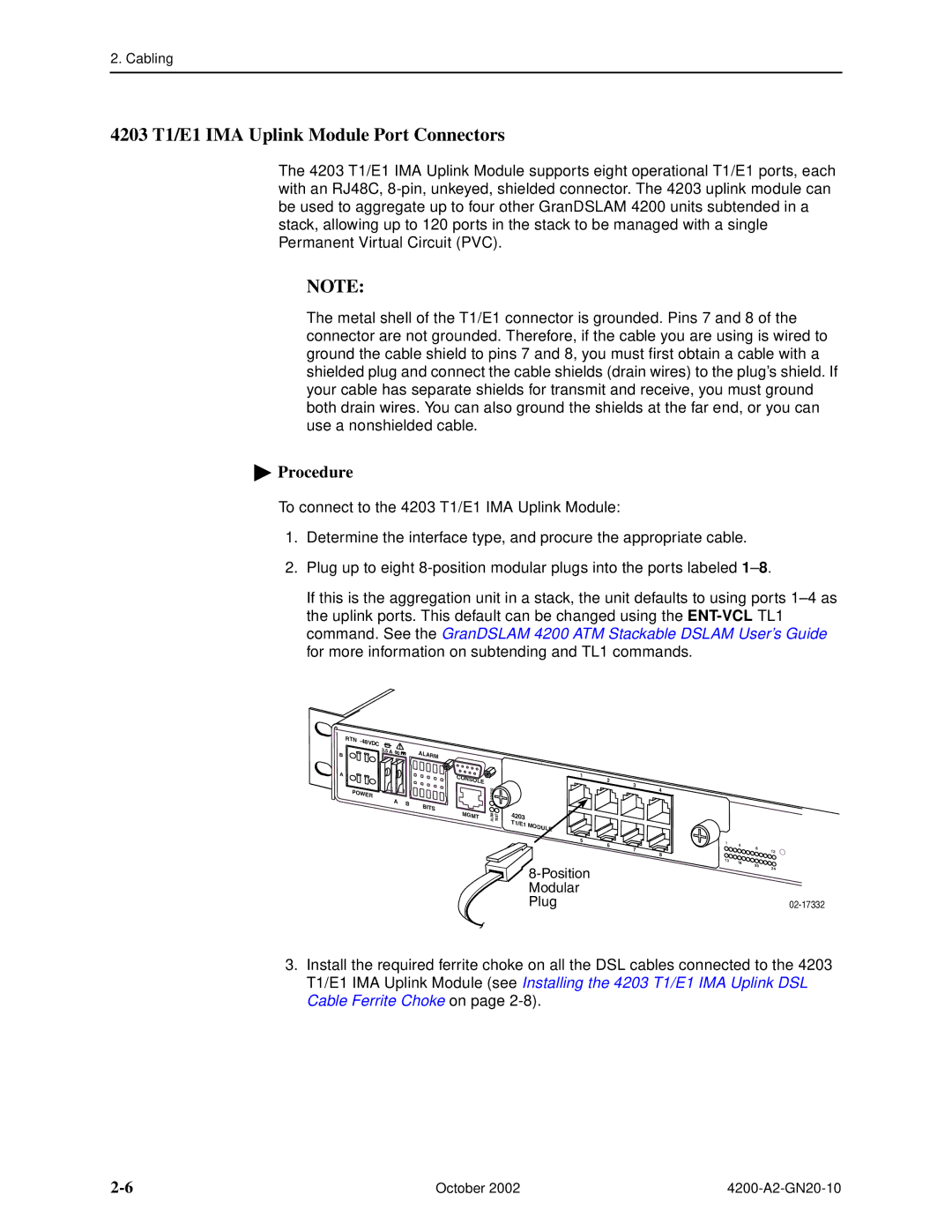
The 4203 T1/E1 IMA Uplink Module supports eight operational T1/E1 ports, each with an RJ48C,
NOTE:
The metal shell of the T1/E1 connector is grounded. Pins 7 and 8 of the connector are not grounded. Therefore, if the cable you are using is wired to ground the cable shield to pins 7 and 8, you must first obtain a cable with a shielded plug and connect the cable shields (drain wires) to the plug’s shield. If your cable has separate shields for transmit and receive, you must ground both drain wires. You can also ground the shields at the far end, or you can use a nonshielded cable.
 Procedure
To connect to the 4203 T1/E1 IMA Uplink Module:
1.Determine the interface type, and procure the appropriate cable.
2.Plug up to eight
If this is the aggregation unit in a stack, the unit defaults to using ports
R | - |
TN | |
| 48VDC |
B3.5 A 60![]()
A![]()
![]()
PO |
|
WER |
|
A | B |
|
A |
|
LARM |
|
C |
|
ONS |
|
OLE |
|
| SU KIN TAT LP S U |
B |
|
ITS |
|
M |
|
GMT | MR T LA SET |
1 | 2 |
|
|
| 3 |
| |
|
| 4 | |
|
|
|
4203 |
|
|
|
|
T1/E1 | MODULE |
|
|
|
|
|
|
| |
| 5 | 6 |
|
|
|
| 7 |
| |
|
|
| 8 | |
|
|
|
|
1 | 4 |
|
|
| 8 |
| |
|
| 12 | |
|
|
| |
13 | 16 |
|
|
| 20 |
| |
|
| 24 | |
|
|
|
3.Install the required ferrite choke on all the DSL cables connected to the 4203 T1/E1 IMA Uplink Module (see Installing the 4203 T1/E1 IMA Uplink DSL Cable Ferrite Choke on page
October 2002 |
