2. Cabling
Uplink Module Connectors
he following types of uplink modules are available for the unit:
Model 4201 T1 Uplink Module
TModel 4202 E1 Uplink Module
Model 4203 T1/E1 IMA Uplink Module
4201 T1 Uplink Module Connector
The 4201 T1 Uplink Module has a single RJ48C,
NOTE:
The metal shell of the T1 connector is grounded. Pins 7 and 8 of the connector are not grounded. Therefore, if the cable you are using is wired to ground the cable shield to pins 7 and 8, you must first obtain a cable with a shielded plug and connect the cable shields (drain wires) to the plug’s shield. If your cable has separate shields for transmit and receive, you must ground both drain wires. You can also ground the shields at the far end, or you can use a nonshielded cable.
 Procedure
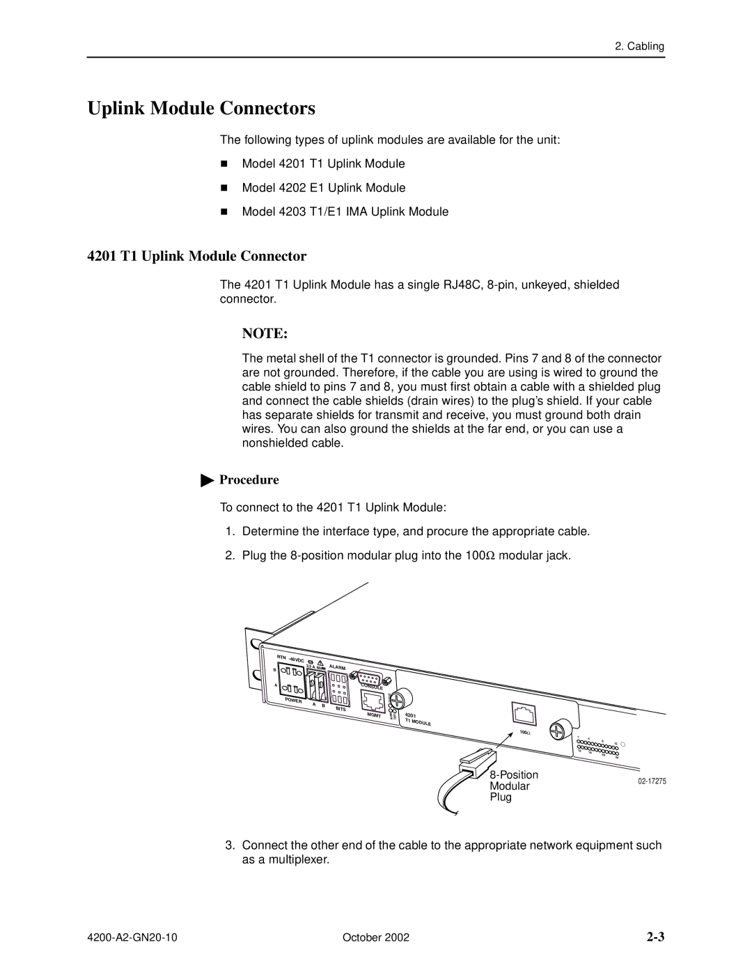
To connect to the 4201 T1 Uplink Module:
1. Determine the interface type, and procure the appropriate cable.
2. Plug the
RTN - |
|
|
|
|
48VDC | 3.5 |
|
| ALAR |
B | A | 60 | ||
|
|
| M | |
A |
|
|
| C |
|
|
|
| ONS |
|
|
|
| OLE |
PO |
|
|
|
|
WER |
| A | B |
|
|
| B | ||
|
|
| ||
|
|
|
| ITS |
|
|
|
| M |
|
|
|
| GMT |
S | K |
U | |
T | IN |
A L | |
T P | |
S U | |
MT R S L E A T
4201 T1 MODULE
100Ω
1 | 4 |
|
| 8 | 12 |
|
| |
13 | 16 |
|
| 20 | 24 |
|
|
Modular02-17275
Plug
3.Connect the other end of the cable to the appropriate network equipment such as a multiplexer.
October 2002 |