1. Installation
Mounting Configurations
hree basic installation configurations are available:
Rack mount – see Installing the Brackets for Rack Mounting on page
Installing the GranDSLAM 4200 Into a Rack on page
TWall mount – see Installing the GranDSLAM 4200 on a Wall on page
Shelf or desktop – see Installing the GranDSLAM 4200 on a Shelf or Desktop on page
Mounting Brackets
Your GranDSLAM 4200 can be installed in a rack or on the wall using mounting brackets. Two brackets suitable for a
NOTE:
In this guide, the term rack refers to any rack, cabinet, frame, or bay suitable for mounting telecommunications equipment.
Installing the Brackets for Rack Mounting
 Procedure
To install the mounting brackets for rack mounting:
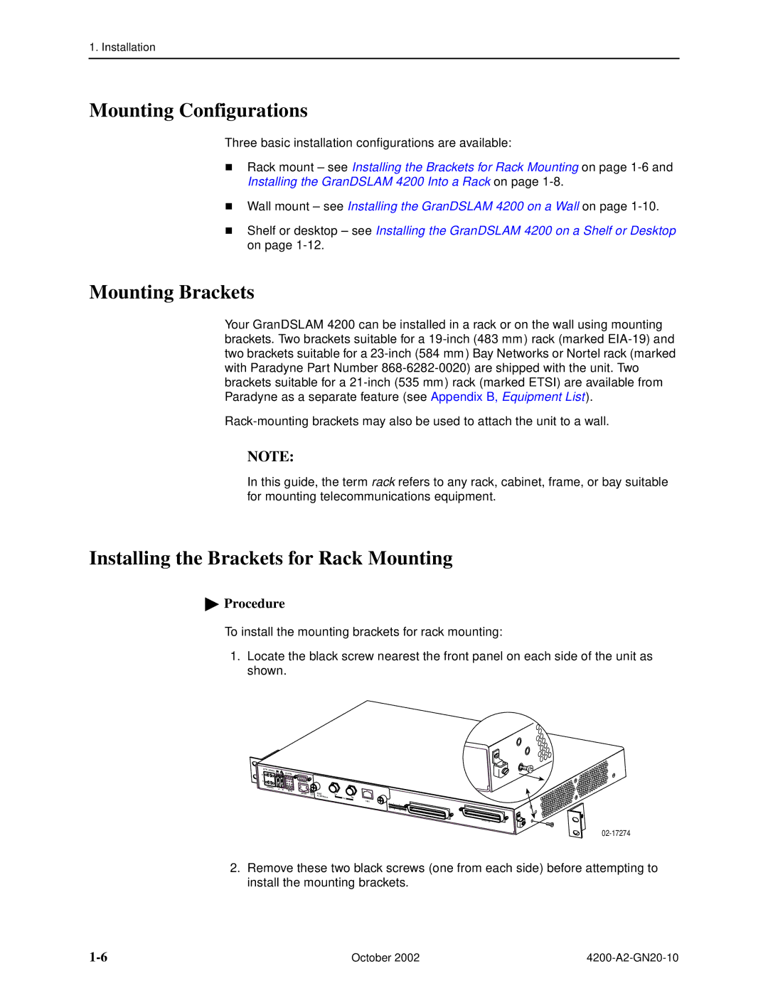
1.Locate the black screw nearest the front panel on each side of the unit as shown.
| RTN |
|
B | 3.5 A 60 | ALARM |
A | CONSOLE |
POWER | A | B |
|
| BITS | ||
|
|
|
MGMT | 4202 | |
| E1 | MODULE |
TX
75Ω | RX |
120Ω
1 | 4 |
| 8 | 12 |
13 | 16 |
|
| 20 | 24 |
DSL PORTS
POTS
2.Remove these two black screws (one from each side) before attempting to install the mounting brackets.
October 2002 |