Connectors and Pin Assignments
A
Overview
he following sections provide pin assignments for: Management Port Connector on page
DSL Ports and POTS Splitter Connectors on page
Management Port Connector on page
Console Port Connector on page
Model 4210 ALARM/BITS Connector on page
T4202 E1 Uplink Module Connectors on page
4203 T1/E1 IMA Uplink Module Port Connectors on page
RTN ![]()
![]() ALARM
ALARM
3.5 A 60
B
A
POWER A B BITS
CONSOLE
MGMT
STATUS | UPLINK |
ALRM | TEST |
TX |
| RX | 1 | 4 | 8 | 12 |
| 100/120Ω |
|
| POTS | ||
4202 | 75Ω |
|
|
|
| |
|
|
|
|
| ||
E1 MODULE |
|
| 13 | 16 | 20 | 24 |
|
|
|
|
|
| DSL PORTS |
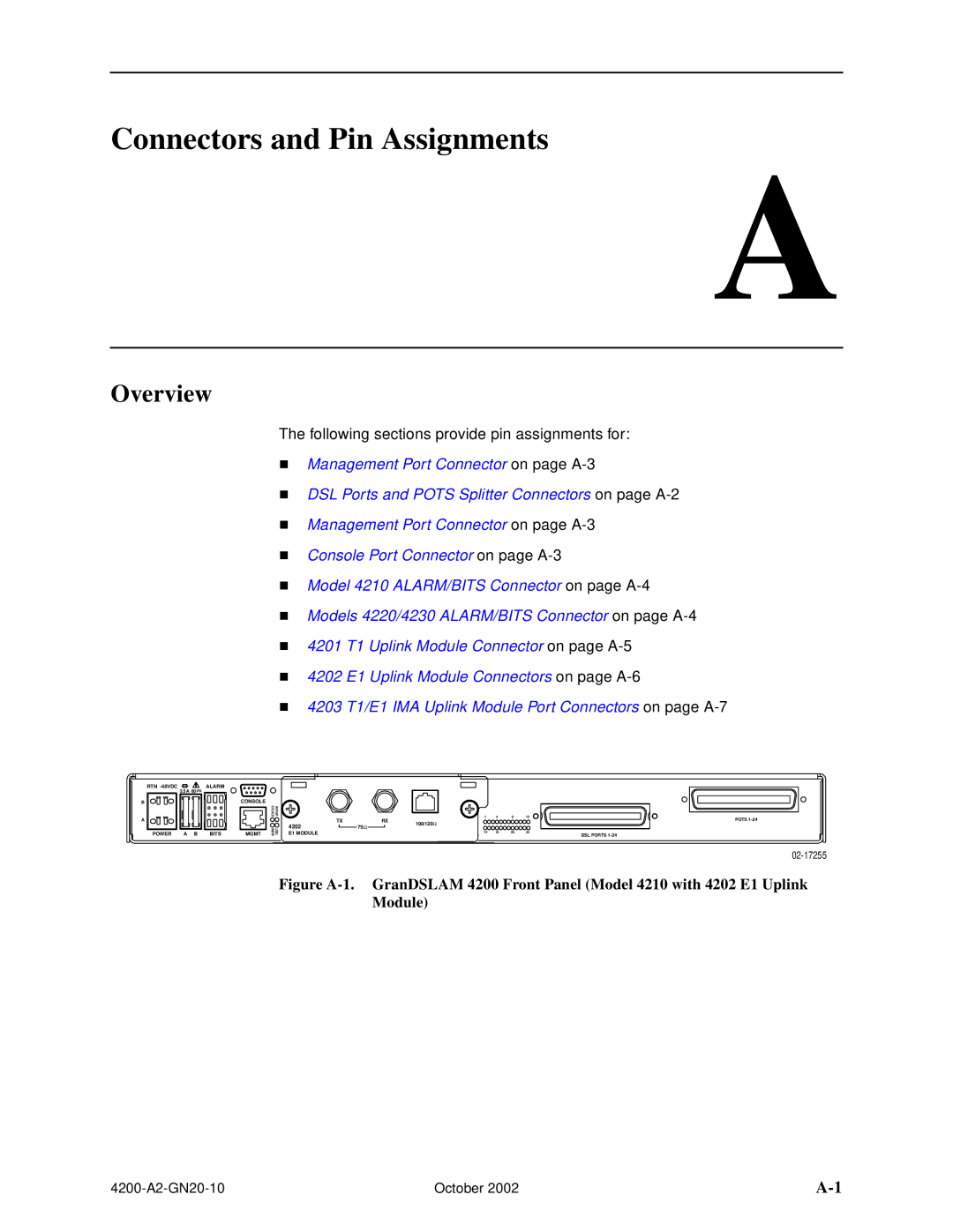
Figure A-1. GranDSLAM 4200 Front Panel (Model 4210 with 4202 E1 Uplink Module)
October 2002 |