1. Installation
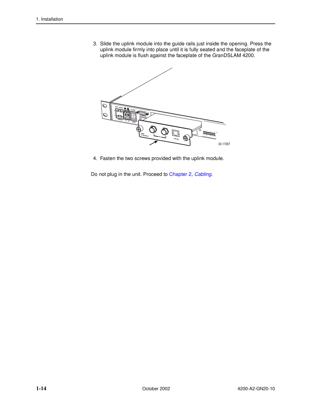
3.Slide the uplink module into the guide rails just inside the opening. Press the uplink module firmly into place until it is fully seated and the faceplate of the uplink module is flush against the faceplate of the GranDSLAM 4200.
RTN - |
|
|
|
|
48VDC | 3.5 A |
|
| ALARM |
B | 60 |
| ||
|
|
| ||
A |
|
|
| CONSOLE |
POWER | A |
| B | STATUS UPLINK |
|
| BITS | ||
|
|
|
|
4202 E1 MODULE
TX
75Ω | RX |
1 | 4 |
|
| 8 | 12 |
13 | 16 |
|
|
| |
| 20 | 24 |
100/120Ω
02-17267
4.Fasten the two screws provided with the uplink module.
Do not plug in the unit. Proceed to Chapter 2, Cabling.
October 2002 |