Paradyne GranDSLAM 4200 manual 4203 T1/E1 IMA Uplink Module Port Connectors

Models: GranDSLAM 4200

1 68
Download 68 pages 25.78 Kb
Page 57
Image 57

A. Connectors and Pin Assignments

4203 T1/E1 IMA Uplink Module Port Connectors

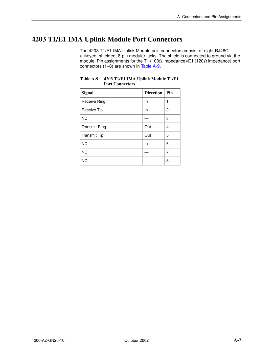
The 4203 T1/E1 IMA Uplink Module port connectors consist of eight RJ48C, unkeyed, shielded, 8-pin modular jacks. The shield is connected to ground via the module. Pin assignments for the T1 (100impedance)/E1 (120impedance) port connectors (1–8) are shown in Table A-9.

Table A-9. 4203 T1/E1 IMA Uplink Module T1/E1

Port Connectors

Signal

Direction

Pin


Receive Ring

In

1


Receive Tip

In

2


NC

3


Transmit Ring

Out

4


Transmit Tip

Out

5


NC

In

6


NC

7


NC

8


4200-A2-GN20-10

October 2002

A-7

Page 57
Image 57
Paradyne GranDSLAM 4200 manual 4203 T1/E1 IMA Uplink Module Port Connectors