The front panel design may differ by chassis. A front panel module mainly consists of power switch, reset switch, power LED, hard drive activity LED, speaker and etc. When connecting your chassis front panel module to this header, make sure the wire assignments and the pin
Chassis Speaker Header |
|
|
| Please connect the chassis |
|
|
| speaker to this header. | |
(see p.13 No. 10) |
|
|
|
|
|
|
|
| |
Chassis and Power Fan Connectors |
|
| Please connect the fan cables | |
|
|
| to the fan connectors and | |
(see p.13 No. 6) |
|
|
| match the black wire to the |
|
|
| ground pin. | |
FAN_SPEED_CONTROL |
|
| ||
(see p.13 No. 27) | PWR_FAN_SPEED | |||
| +12V | |||
GND
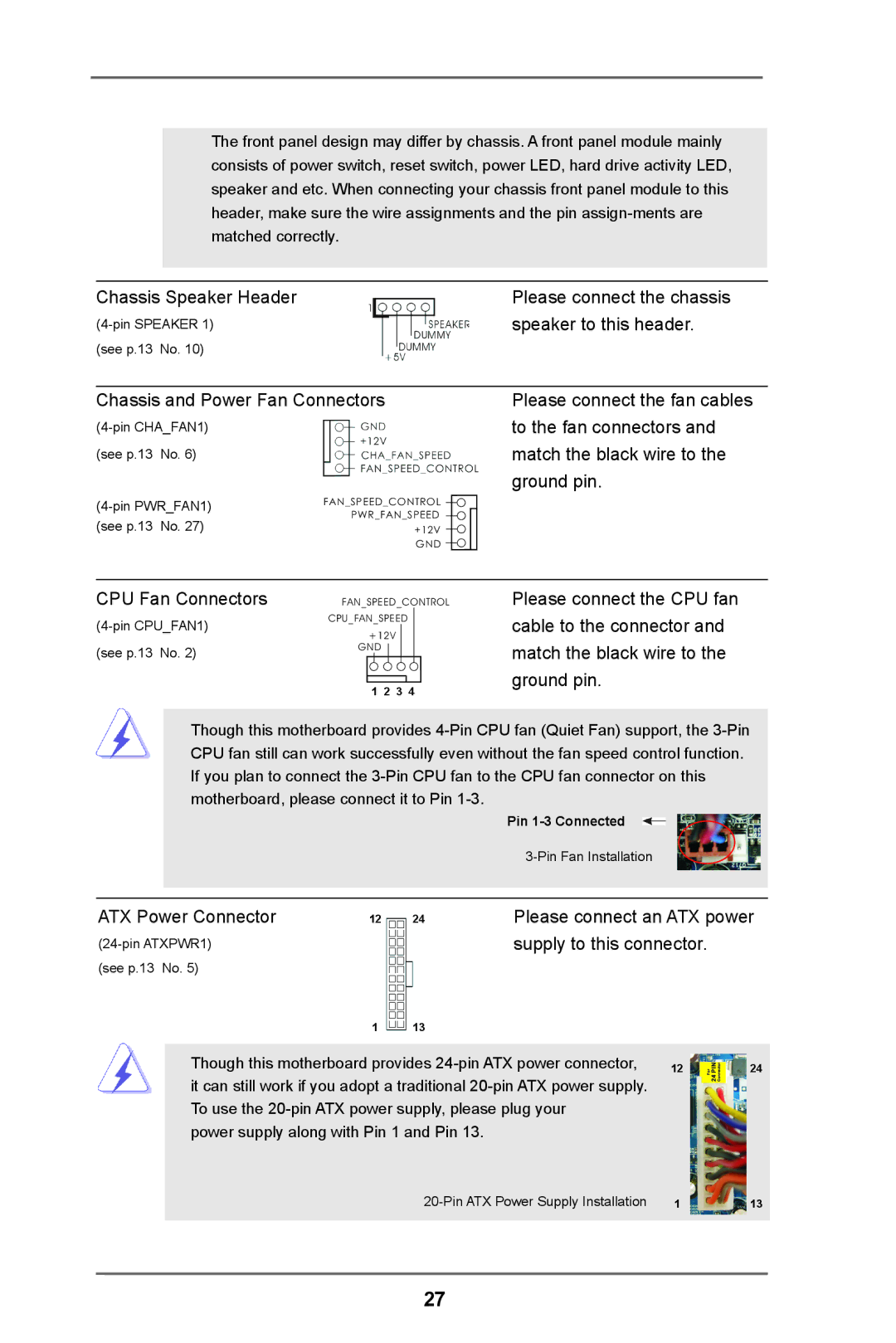
CPU Fan Connectors | FAN_SPEED_CONTROL | |
CPU_FAN_SPEED | ||
+12V | ||
| ||
(see p.13 No. 2) | GND | |
| ||
| 1 2 3 4 |
Please connect the CPU fan cable to the connector and match the black wire to the ground pin.
Though this motherboard provides
|
|
| Pin |
|
|
| |
|
|
|
|
ATX Power Connector | 12 | 24 | Please connect an ATX power |
|
| supply to this connector. | |
(see p.13 No. 5) |
|
|
|
113
Though this motherboard provides | 12 |
| 24 |
| |||
it can still work if you adopt a traditional |
|
|
|
To use the |
|
|
|
power supply along with Pin 1 and Pin 13. |
|
|
|
1 | 13 | ||
|
|
|
|
27