2.7 Onboard Headers and Connectors
Onboard headers and connectors are NOT jumpers. Do NOT place jumper caps over these headers and connectors. Placing jumper caps over the headers and connectors will cause permanent damage of the motherboard!
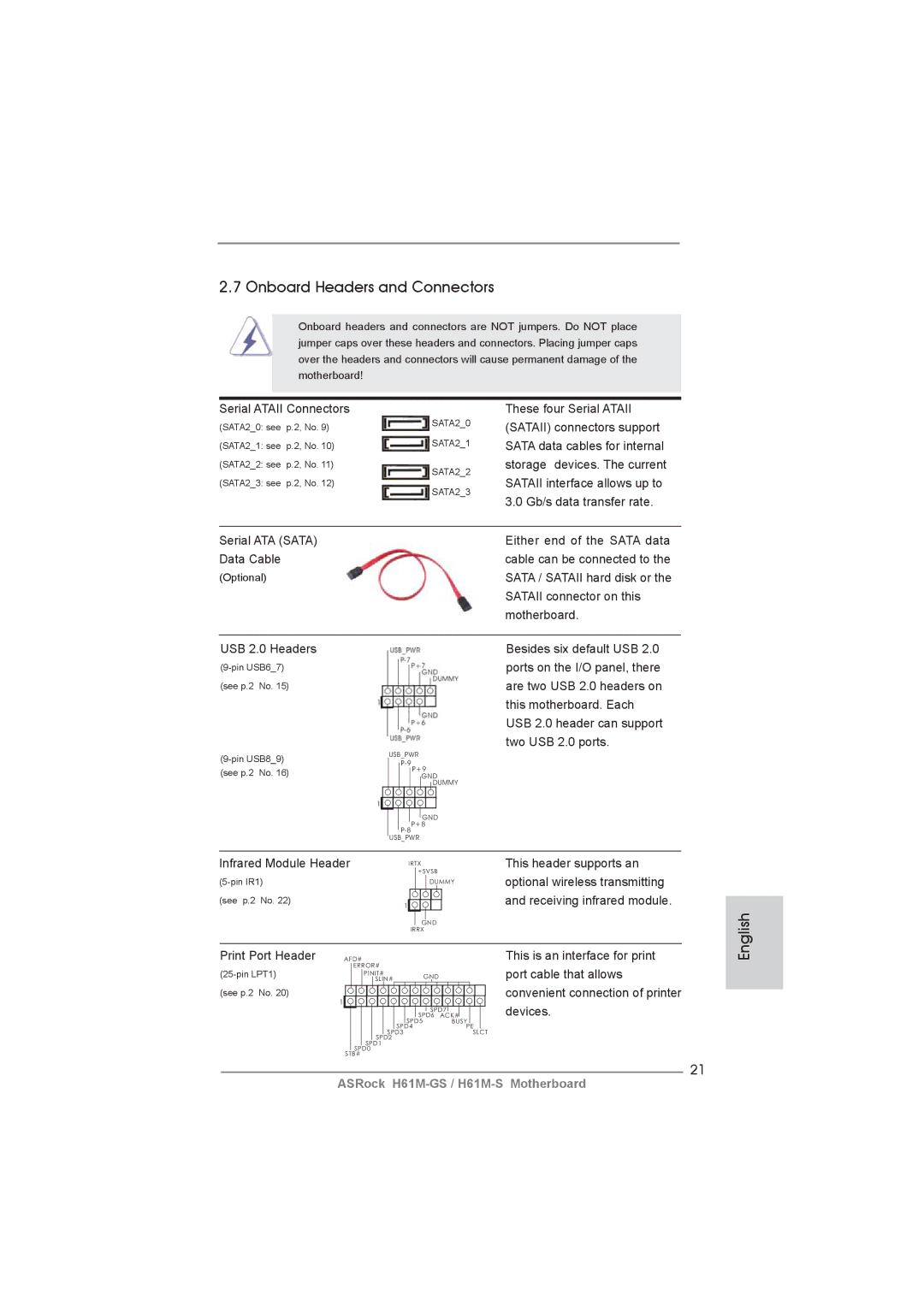
Serial ATAII Connectors
(SATA2_0: see | p.2, No. 9) | SATA2_0 | |
| |||
(SATA2_1: see p.2, No. 10) | SATA2_1 | ||
(SATA2_2: see | p.2, No. 11) | SATA2_2 | |
(SATA2_3: see | p.2, No. 12) | ||
SATA2_3 | |||
|
| ||
These four Serial ATAII (SATAII) connectors support SATA data cables for internal storage devices. The current SATAII interface allows up to 3.0 Gb/s data transfer rate.
Serial ATA (SATA) |
|
|
|
|
|
|
|
|
|
|
|
| Either end of the SATA data |
Data Cable |
|
|
|
|
|
|
|
|
|
|
|
| cable can be connected to the |
(Optional) |
|
|
|
|
|
|
|
|
|
|
|
| SATA / SATAII hard disk or the |
|
|
|
|
|
|
|
|
|
|
|
|
| SATAII connector on this |
|
|
|
|
|
|
|
|
|
|
|
|
| motherboard. |
|
|
|
|
|
|
|
|
|
|
|
|
|
|
USB 2.0 Headers |
|
|
|
|
|
|
|
|
|
|
|
| Besides six default USB 2.0 |
|
|
|
|
|
|
|
|
|
|
|
| ports on the I/O panel, there | |
(see p.2 No. 15) |
|
|
|
|
|
|
|
|
|
|
|
| are two USB 2.0 headers on |
|
|
|
|
|
|
|
|
|
|
|
|
| this motherboard. Each |
|
|
|
|
|
|
|
|
|
|
|
|
| USB 2.0 header can support |
|
|
|
|
|
|
|
|
|
|
|
|
| two USB 2.0 ports. |
|
| USB_PWR |
| ||||||||||
|
|
|
|
|
| ||||||||
(see p.2 No. 16) |
|
|
|
|
|
|
| P+9 |
| ||||
|
|
|
|
|
|
|
| GND |
| ||||
| 1 |
|
|
|
|
|
|
|
| DUMMY |
| ||
|
|
|
|
|
|
|
|
|
|
|
|
| |
|
|
|
|
|
|
|
|
|
|
|
|
| |
|
|
|
|
|
|
|
|
| GND |
| |||
|
|
|
|
|
|
|
| P+8 |
| ||||
|
|
|
|
|
| ||||||||
|
|
| USB_PWR |
| |||||||||
|
|
|
|
|
|
|
|
|
|
|
|
|
|
Infrared Module Header |
|
|
|
|
|
| IRTX | This header supports an | |||||
|
|
|
|
|
|
|
| +5VSB | optional wireless transmitting | ||||
|
|
|
|
|
|
|
| DUMMY | |||||
(see p.2 No. 22) | 1 |
|
|
|
|
|
| and receiving infrared module. | |||||
|
|
|
|
|
| ||||||||
|
|
|
|
|
| ||||||||
|
|
|
|
|
|
|
|
|
|
|
| ||
|
|
|
|
|
|
|
|
| GND |
| |||
|
|
|
|
|
|
|
| IRRX |
| ||||
English
Print Port Header | AFD# |
|
ERROR# | GND | |
PINIT# | ||
| SLIN# |
|
(see p.2 No. 20) |
|
|
| 1 |
|
|
| SPD7 |
| SPD6 ACK# | |
| SPD5 | BUSY |
| SPD4 | PE |
| SPD3 | SLCT |
| SPD2 |
|
| SPD1 |
|
| SPD0 |
|
| STB# |
|
This is an interface for print port cable that allows convenient connection of printer devices.
21
ASRock