Infringe
Copyright Notice
DTS, Inc., All Rights Reserved
Z87 Extreme6/ac
Motherboard Layout
Z87 Extreme6
No. Description
Chassis Fan Connector CHAFAN2
Optical Spdif Out Port
Panel
Speed LED Status Description
Off No Link Blinking Data Activity
Introduction
Package Contents
Specifications
Audio
Graphics
Ac only
Wireless
For Z87
Extreme6
Support
Connector
Feature
Storage
Tions
Hardware
Certifica
FCC, CE, Whql
ASRock A-Tuning
Unique Features
ASRock Uefi System Browser
ASRock Easy Driver Installer
ASRock FAN-Tastic Tuning
WiFi + BT Module
Installing the SMA Wi-Fi Antenna Cables
Fasten the screw nuts to secure the connec- tors
Installation
Installing the CPU
English
English
Installing the CPU Fan and Heatsink
Dual Channel Memory Configuration
Installing Memory Modules Dimm
English
Expansion Slots PCI and PCI Express Slots
MINIPCIE1 mini-PCIe slot is used for WiFi module
See p.1 or p.2, No
Jumpers Setup
Default
CLRCMOS1
Pwrbtn Power Switch
Onboard Headers and Connectors
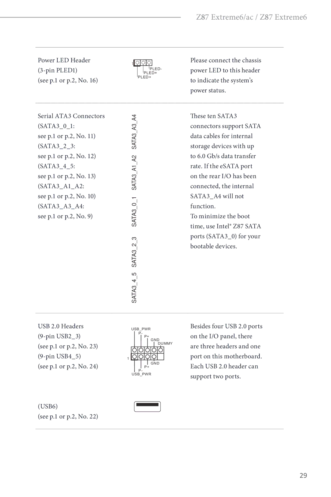
Bootable devices
Power LED Header 3-pin PLED1 See p.1 or p.2, No
Power status
To minimize the boot
Header can support two ports
USB 3.0 Headers
Chassis Speaker Header
Chassis and Power Fan Connectors
Pin SPEAKER1 Speaker to this header See p.1 or p.2, No
This COM1 header supports a serial port module
PWR1
Pwrbtn
Smart Switches
Rstbtn
Lieferumfang
Einleitung
Technische Daten
Unterstützt Purity Sound
Headsets mit bis zu 600 Ohm
Audiocodec
Erstklassige Blu-ray-Audiounterstützung
Rückblende
Wireless LAN
Nur beim Z87
Extreme6/ac
Anschluss
Betriebssystem
Support-CD
Zertifizierungen
Siehe S oder S , Nr
Jumpereinstellung
CMOS-löschen-Jumper
Standard
Verbinden Sie
Integrierte Stiftleisten und Anschlüsse
Interne Speichergeräte
Bootfähigen Geräte
Diese zehn SATA-III
SATA-Datenkabel für
Polig, HDAUDIO1
USB 3.0-Stiftleisten
Audiostiftleiste
Frontblende
Polig, SPEAKER1
Gehäuselautsprecherstift
Bitte verbinden Sie den
Leiste
Polig, SLI/XFIRE Anschluss mit einem
Installiert sind
Intelligente Schalter
BIOSSEL1
Clrcbtn
Contenu de l’emballage
Spécifications
Graphiques
Uniquement
Réseau
Réseau sans
Fil pour Z87
Stockage
’exploitation Certifications
CD inclus
Surveillance
Système
Voir p.1 ou p.2, No
Configuration des cavaliers Jumpers
Cavalier Clear Cmos
Par défaut
PANNEAU1 à 9 broches Voir p.1 ou p.2, No
Embases et connecteurs de la carte mère
Embase du panneau
Système
USB6 Voir p.1 ou p.2, No
USB345 à 19 broches voir p.1 ou p.2, No
Embases USB
Connecteur d’alimentation
Embase du haut-parleur
Du châssis
SPEAKER1 à 4 broches Embase
Cette embase COM1 prend en charge un module de port série
Voir p.1 ou p.2, No Cartes graphiques sont
Cmos Clrcbtn
Boutons intelligents
Marche permet aux
Réinitialisation permet aux
Contenuto della confezione
Introduzione
Specifiche
Grafica
Posteriore
LAN wireless
Solo per Z87
Pannello
Connettore
Del Bios
Caratteristiche
Supporto
CD di
Certificazioni
Predefinito
Impostazione jumper
Jumper per azzerare la
Cmos
Header sul pannello del sistema
Header e connettori sulla scheda
USB6 Vedere pag o 2, n
Header USB 3.0 USB345 a 19 pin vedere pag o 2, n
Questa scheda madre è 3dotata di un connettore2
Header altoparlante
Chassis Chassis a questo header SPEAKER1 a 4 pin
Vedere pag.1 o 2, n
Header modulo infrarossi IR1 a 5 pin Vedere pag o 2, n
Connettore alimentazione Collegare questo
SLI/XFIRE
Madre
Di accendere/spegnere
Interruttori intuitivi
Interruttore ’interruttore ’alimentazione
’alimentazione consente
Contenido del paquete
Introducción
Especificaciones
Gráficos
Panel trasero
LAN inalám
Brica sólo
Para Z87
Ento
Almacenami
Conectores
Monitor del
CD de soporte
Certificaciones
Puente de borrado de Cmos
Instalación de los puentes
Consulte la pág.1 ó 2, N.º Predeterminado Borrado de Cmos
Pwrbtn Interruptor de alimentación
Conectores y cabezales incorporados
Sata para dispositivos
Estos diez conectores
SATA3 son compatibles
Con cables de datos
Consulte la pág.1 ó 2, N.º
Esta placa base contiene Un conector de
Cabezal de altavoces del
Chasis
SPEAKER1 de 4 pines
Base
Conector de alimentación
Con un conector de
SLI/XFIREPWR1 de
Interruptores inteligentes
Bios B
Комплект поставки
Введение
Спецификация
Система
Графическая
Аудио
Treme6/ac
Беспроводная
ЛВС только
Для Z87 Ex
Особенности
Запоминающие
Устройства
Разъемы
Контроль
Диск с ПО
Сертификация
Установка перемычек
Колодка системной панели 9-контактная, PANEL1 См. стр или 2
Колодки и разъемы, расположенные на материнской плате
USB6 См. стр или 2
AUDIO1
ATXPWR1
FAN1
FAN2
FAN3
XFIREPWR1
Xfire
Для быстрого обнуления
Селекторный Селекторный переключатель Переключатель Bios
Электронные кнопки
Cmos предназначена
Conteúdo da embalagem
Introdução
100
Especificações
Áudio
101
Do painel
102
LAN sem
Fiosapenas
103
Certificações
104
Sistema
Operativo
Consultar p.1 ou p.2, N.º Predefinição Limpar Cmos
Configuração dos jumpers
105
Jumper para limpar o Cmos
106
Terminais e conectores integrados
Terminal do painel de siste- ma
USB6 Consultar p.1 ou p.2, N.º
107
Estes dez conectores SATA3 suportam
De arranque, utilize
Terminal de áudio do painel frontal
108
CPU
109
Este terminal COM1 suporta um módulo de porta de série
110
Conector de alimentação
Placa principal
111
112
Ambalaj İçeriği
113
Özellikler
Grafikler
114
Ses
115
Bağlayıcı
Bios Özelliği
116
Depolama
Belgeler
117
Destek CDsi
Donanım
Varsayılan CMOSu Temizle
Bağlantı Teli Kurulumu
118
CMOSu Temizle Bağlantı Teli
119
Kart Üzerindeki Bağlantı ve Konektörler
Bkz. sf.1 veya sf.2, No
Bkz. sf.1 veya sf.2, No 9-pin USB45 USB6
120
121
Bu anakart, 4-Pin CPU
122
Kasa Hoparlör Bağlantısı
Pin SPEAKER1 Bu bağlantıya takın
Bu COM1 bağlantısı seri bağlantı yuvası modülünü destekler
123
Pinli SLI/XFIRE Takılıyken lütfen bu
Bağlayıcıyı sabit disk güç
124
Akıllı Anahtarlar
125
포장 내용물
DDR3 Dimm 슬롯 4 개
126
스타일
ATX 폼 팩터
127
무선 LAN Z87
128
IR 헤더 1 개
Bios 기능
Smbios 2.3.1 지원 CPU, DRAM, PCH 1.05V, PCH 1.5V 전압 다중 조정
129
ErP/EuP 사용 가능 ErP/EuP 사용 가능 전원공급장치 필요
130
전압 모니터링 +12V, +5V, +3.3V, CPU Vcore
Microso Windows 8 / 8 64 비트 / 7 / 7 64 비트 호환
페이지 또는 2 페이지 ,기본값 Clear Cmos 14 번 항목 참조
점퍼 설정
131
Clear Cmos 점퍼
132
온보드 헤더 및 커넥터
PANEL1
133
USB 3.0 헤더 19 핀 USB345
134
HDAUDIO1
135
IR1
136
SLI/XFIRE 전원 커넥터
SLI/XFIREPWR1
스마트 스위치
BIOSSEL11 페이지 또
137
138
はじめに
DDR3 Dimm スロット
WiFi 802.11ac (Z87 Extreme6/ac 専用)
139
HDMI-IN
差動アンプによる 115dB SNR DAC
140
4400/4600 Pixel Shader 5.0, DirectX
Purity Sound をサポート
LAN (Z87
141
ギガビット LAN 10/100/1000 Mb/ 秒
Ieee 802.11a/b/g/n/ac をサポート
142
ErP/EuP Ready(ErP/EuP ready 電源が必要です)
143
電圧監視:+12V 、+5V 、+3.3V 、CPU Vcore
FCC 、CE 、WHQL
14)
144
145
オンボードのヘッダーとコネクター
146
(9 ピン HDAUDIO1)
147
USB 3.0 ヘッダー (19 ピン USB345)
(19 ピン USB367)
148
(4 ピン SLI/XFIREPWR1)
149
(9 ピン COM1)
(RSTBTN)
(BIOSSEL1)
150
(PWRBTN)
151
包装清单
152
153
支持 Dual LAN with Teaming(双网卡网络整合)
支持 Bluetooth 4.0 / 3.0 + 高速 Class
154
支持 Wake-On-LAN(网上唤醒)
155
认证 FCC、CE、WHQL ErP/EuP 支持(需要支持 ErP/EuP 的电源)
156
电压监控: +12V 、+5V 、+3.3V 、CPU Vcore
Microso Windows 8 / 8 64-bit / 7 / 7 64-bit 兼容
157
跳线设置
158
板载接脚和接口
159
USB 3.0 接脚 19 针 USB345
160
19 针 USB367
161
(4 针 SLI/XFIRE
162
PWR1)
163
Bios a 或 Bios B 中引导。
164
電子信息產品污染控制標示
感謝您購買 ASRock Z87 Extreme6/ac / Z87 Extreme6 主機板,本主機板經
165
DDR3 Dimm 插槽
166
ATX 尺寸
雙層堆疊 Mosfet DSM 支援 Intel Turbo Boost 2.0 技術
EMI 遮蔽蓋 PCB 隔離遮蔽 支援 DTS Connect
167
Pixel Shader 5.0,DirectX
三個 VGA 輸出選項: DVI-I、HDMI 及 DisplayPort
LED)
168
169
Bios 功能
IR 排針
電壓監控:+12V 、+5V 、+3.3V 、CPU Vcore
170
ErP/EuP Ready(需具備 ErP/EuP ready 電源供應器)
171
跳線設定
Pin PANEL1
172
接背後 I/O 上的 eSATA 連接埠,內部 SATA3A4
173
Pin PLED1
Pin USB45
Pin HDAUDIO1
174
USB 3.0 排針 Pin USB345
Pin USB367
175
Pin SLI/XFIREPWR1
176
Pin IR1
177
Bios 選擇開關
178
Isi Kemasan
Perhatian
Spesifikasi
179
Memori
Grafis
180
Panel I/O
181
LAN Nirkabel
Hanya untuk
Konektor
Fitur Bios
182
Penyimpanan
Sertifikasi
183
Perangkat
Keras
184
Konfigurasi Jumper
Lihat hal.1 atau hal.2, No
185
Header dan Konektor Onboard
186
187
188
189
190
Tombol Pintar
Page
Page
Contact Information
EC-Declaration of Conformity