DANGER. Before using an adapter as illustrated, be certain that the center screw of the outlet plate is grounded. The
NOTE: USE OF AN ADAPTER IS NOT ALLOWED IN CANADA. IF A GROUNDING TYPE RECEPTACLE IS NOT AVAILABLE, DO NOT USE THIS APPLIANCE UNTIL THE PROPER OUTLET IS INSTALLED BY A QUALIFIED ELECTRICIAN.
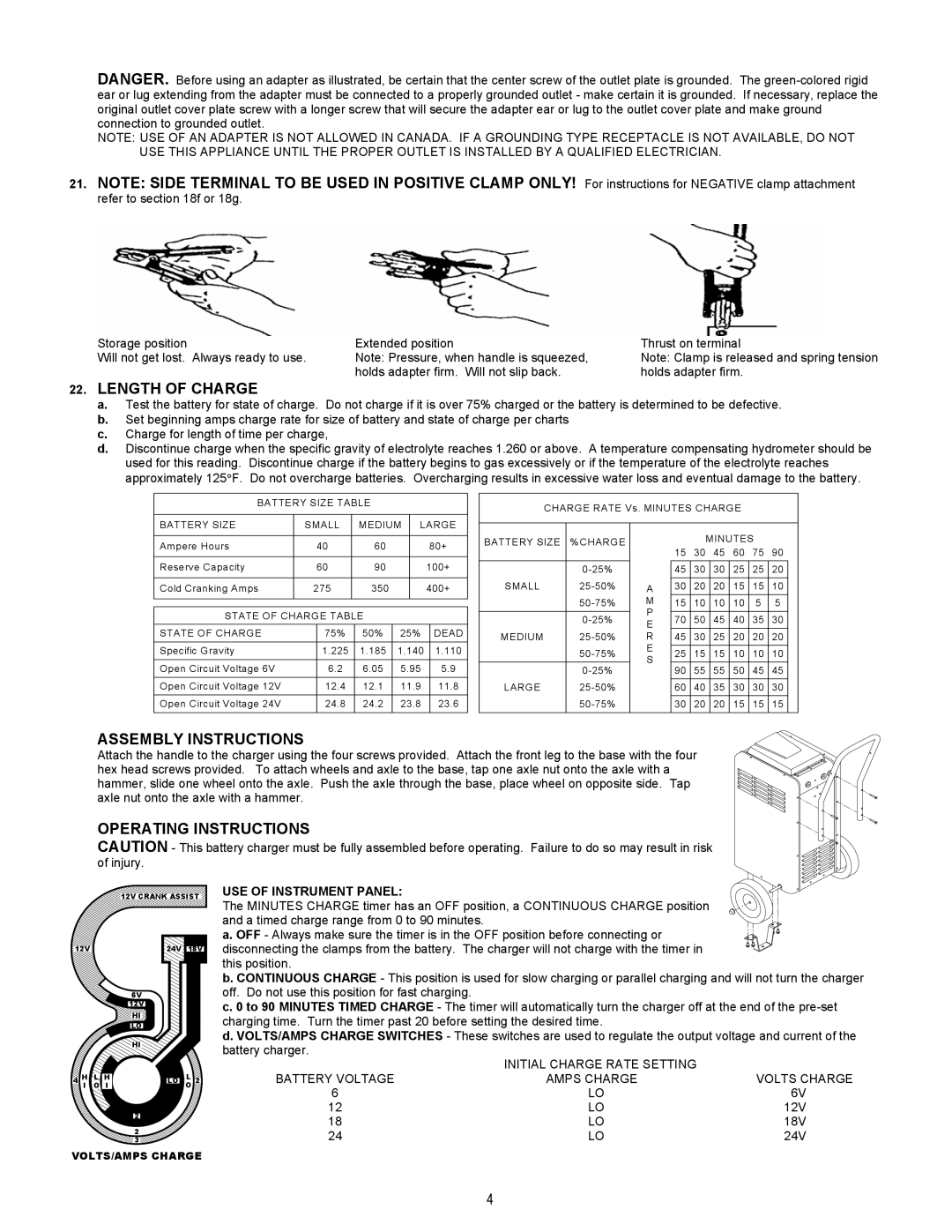
21.NOTE: SIDE TERMINAL TO BE USED IN POSITIVE CLAMP ONLY! For instructions for NEGATIVE clamp attachment
refer to section 18f or 18g.
Storage position | Extended position |
Will not get lost. Always ready to use. | Note: Pressure, when handle is squeezed, |
| holds adapter firm. Will not slip back. |
Thrust on terminal
Note: Clamp is released and spring tension holds adapter firm.
22.LENGTH OF CHARGE
a.Test the battery for state of charge. Do not charge if it is over 75% charged or the battery is determined to be defective.
b.Set beginning amps charge rate for size of battery and state of charge per charts
c.Charge for length of time per charge,
d.Discontinue charge when the specific gravity of electrolyte reaches 1.260 or above. A temperature compensating hydrometer should be used for this reading. Discontinue charge if the battery begins to gas excessively or if the temperature of the electrolyte reaches approximately 125°F. Do not overcharge batteries. Overcharging results in excessive water loss and eventual damage to the battery.
BATTERY SIZE TABLE
CHARGE RATE Vs. MINUTES CHARGE
BATTERY SIZE | SMALL |
| MEDIUM | LARGE | ||||
|
|
|
|
|
|
|
|
|
Ampere Hours | 40 | 60 |
|
| 80+ | |||
|
|
|
|
|
|
|
|
|
Reserve Capacity | 60 | 90 |
|
| 100+ | |||
|
|
|
|
|
|
|
|
|
Cold Cranking Amps | 275 | 350 |
|
| 400+ | |||
|
|
|
|
|
|
|
|
|
|
|
|
|
|
|
|
|
|
STATE OF CHARGE TABLE |
|
|
|
| ||||
|
|
|
|
|
|
|
|
|
STATE OF CHARGE |
| 75% |
| 50% | 25% |
| DEAD | |
|
|
|
|
|
|
|
|
|
Specific Gravity |
| 1.225 |
| 1.185 | 1.140 |
| 1.110 | |
|
|
|
|
|
|
|
|
|
Open Circuit Voltage 6V |
| 6.2 |
| 6.05 | 5.95 |
| 5.9 | |
Open Circuit Voltage 12V |
| 12.4 |
| 12.1 | 11.9 |
| 11.8 | |
Open Circuit Voltage 24V |
| 24.8 |
| 24.2 | 23.8 |
| 23.6 | |
|
|
|
|
|
|
|
|
|
BATTERY SIZE | %CHARGE |
|
|
| |
SMALL | |
| |
|
|
| |
MEDIUM | |
| |
| |
LARGE | |
| |
|
|
A
M
P E R E S
MINUTES
15 30 45 60 75 90
45 | 30 | 30 | 25 | 25 | 20 |
30 | 20 | 20 | 15 | 15 | 10 |
15 | 10 | 10 | 10 | 5 | 5 |
70 | 50 | 45 | 40 | 35 | 30 |
45 | 30 | 25 | 20 | 20 | 20 |
25 | 15 | 15 | 10 | 10 | 10 |
90 | 55 | 55 | 50 | 45 | 45 |
60 | 40 | 35 | 30 | 30 | 30 |
30 | 20 | 20 | 15 | 15 | 15 |
ASSEMBLY INSTRUCTIONS
Attach the handle to the charger using the four screws provided. Attach the front leg to the base with the four hex head screws provided. To attach wheels and axle to the base, tap one axle nut onto the axle with a hammer, slide one wheel onto the axle. Push the axle through the base, place wheel on opposite side. Tap axle nut onto the axle with a hammer.
OPERATING INSTRUCTIONS
CAUTION - This battery charger must be fully assembled before operating. Failure to do so may result in risk of injury.
|
|
| 12V CRANK ASSIST | |
12V |
| 24V | 18V | |
|
|
| 6V |
|
|
|
| 12V |
|
|
|
| HI |
|
|
|
| LO |
|
|
|
| HI |
|
4 | H | L H | LO | L 2 |
| I | O I |
| O |
2
2
3
VOLTS/AMPS CHARGE
USE OF INSTRUMENT PANEL: The MINUTES CHARGE timer has an OFF position, a CONTINUOUS CHARGE position
and a timed charge range from 0 to 90 minutes.
a. OFF - Always make sure the timer is in the OFF position before connecting or
disconnecting the clamps from the battery. The charger will not charge with the timer in this position.
b. CONTINUOUS CHARGE - This position is used for slow charging or parallel charging and will not turn the charger off. Do not use this position for fast charging.
c. 0 to 90 MINUTES TIMED CHARGE - The timer will automatically turn the charger off at the end of the
d. VOLTS/AMPS CHARGE SWITCHES - These switches are used to regulate the output voltage and current of the battery charger.
BATTERY VOLTAGE | INITIAL CHARGE RATE SETTING |
|
AMPS CHARGE | VOLTS CHARGE | |
6 | LO | 6V |
12 | LO | 12V |
18 | LO | 18V |
24 | LO | 24V |
4