Motherboard
Copyright 2002 ASUSTeK Computer INC. All Rights Reserved
E1006 First Edition May
Contents
Bios setup
Powering up
Software support
Federal Communications Commission Statement
FCC/CDC statements
Vii
Safety information
Electrical safety
Operation safety
How this guide is organized
About this guide
Optional Documentation
Where to find more information
Conventions used in this guide
Asus Websites
ASUSTeK Computer INC. Asia-Pacific
Asus contact information
CPU
P4B533-V specifications summary
Internal I/O
Xii
Chapter
Chapter summary
Welcome
Package contents
Product highlights
Special features
Asus MyLogo2
Digital audio interface
Asus EZ Plug
Asus Post Reporter
Value-added solutions
Auto fan off
Temperature, fan, and voltage monitoring
Dual function power switch
Acpi ready
Major components
Motherboard overview
Asus P4B533-V motherboard user guide
Core specifications
On audio models only
Product introduction
Hardware information
Chapter summary
Screw holes
Motherboard installation
Placement direction
22.86cm 9.0in
Motherboard layout
Before you proceed
Overview
Central Processing Unit CPU
Installing the CPU
Hardware information
Installing the heatsink and fan
Retention Hole Retention Lock
Connecting the CPU fan cable
P4B533-V 184-Pin DDR Dimm Sockets
System memory
Installing a Dimm
Memory configurations
Removing a Dimm
Expansion slots
Installing an expansion card
Configuring an expansion card
IRQ assignments for this motherboard
Standard Interrupt Assignments
AGP slot
PCI slots
JumperFree mode JEN1
Switches and jumpers
Processor system bus selection 3-pin PSBSEL1
CPU external frequency selection DSW1 Switches
CPU CoreBus frequency multiple DSW2 Switches
Vcore over-voltage 3-pin OVERVOLT1
Keyboard power 3-pin KBPWR1
USB device wake-up 3-pin USBPWR12, USBPWR34, USBPWR56
Speaker selector 3-pin SPEECH1
SMB V2.0 setting two 3-pin SMB20
Bass/Center setting 3-pin BCS1, BCS2 on audio models only
Clear RTC RAM CLRTC1
Hard disk activity LED 2-pin IDELED1
Connectors
Floppy disk drive connector 34-1 pin FLOPPY1
IDE connectors 40-1 pin IDE1, IDE2
SMBus connector 6-1 pin SMB1
Chassis intrusion connector 4-1 pin CHASSIS1
P4B533-V ATX & Auxiliary Power Connectors
Smart Card Reader connector 14-1 pin SMARTCON1 optional
USB header 10-1 pin USB56
Power supply thermal connector 2-pin TRPWR1
GAME/MIDI connector 16-1 pin GAME1
Asus iPanel connector 24-1 pin AFPANEL1 optional
Line in connector 5-pin FPLINEIN1 on audio models only
Make sure to remove the caps from the FPLOSWL1
Digital audio connector 6-1 pin SPDIF1 on audio models only
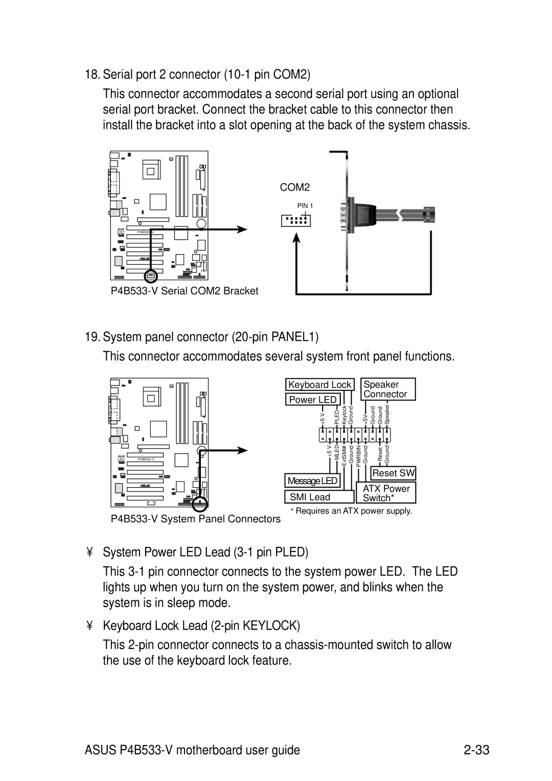
Keyboard Lock Lead 2-pin Keylock
Serial port 2 connector 10-1 pin COM2
System panel connector 20-pin PANEL1
System Power LED Lead 3-1 pin Pled
System Message LED Lead 2-pin Mled
ATX Power Switch / Soft-Off Switch Lead 2-pin Pwrbtn
Reset Switch Lead 2-pin Reset
System Warning Speaker Lead 4-pin Spkr
Powering up
Chapter summary
Starting up for the first time
Award Bios Beep Codes
Post Message Action
Vocal Post Messages
Connector
Powering off the computer
Bios setup
Managing and updating your Bios
Using Asus EZ Flash to update the Bios
Managing and updating your Bios
At the prompt, Please Enter File Name for NEW Bios , type
Creating a bootable disk
Using Aflash to update the Bios
Bios Setup
Updating the Bios
Bios Setup
Bios Setup program
Navigation Keys Function Description
Bios menu bar
Sub-menu
Saving changes and exiting the Setup program
General help
Scroll bar
System Date XX/XX/XXXX
Floppy 3 Mode Support Disabled
Main Menu
System Time
Forgot the password?
Supervisor Password Disabled / User Password Disabled
Halt On All Errors
Installed Memory XXX MB
Type Auto
Primary and Secondary Master/Slave
User Type HDD
Sector
Translation Method LBA
Cylinders
Head
Multi-Sector Transfers Maximum
Smart Monitoring Disabled
PIO Mode
Ultra DMA Mode Disabled
Keyboard Auto-Repeat Rate 6/Sec
Keyboard Features
Boot Up NumLock Status On
Keyboard Auto-Repeat Delay 1/4 Sec
CPU Speed Manual
Advanced Menu
AGP/PCI Frequency MHz 66.66/33.33
AGP/PCI Frequency Setting Auto
CPU VCore Setting Auto
CPU/Memory Frequency Ratio Auto
AGP Vddq Voltage Auto
CPU Level 1 Cache, CPU Level 2 Cache Enabled
DDR Reference Voltage Auto
USB Legacy Support Auto
Bios Update Enabled
OS/2 Onboard Memory 64M Disabled
PS/2 Mouse Function Control Auto
Sdram Configuration By SPD
Chip Configuration
AGP Capability 4X Mode
Sdram Active Precharge Delay value depends on Sdram SPD
Sdram Idle Timer Infinite
Memory Turbo Mode Disabled
Onboard PCI IDE Both
Video Memory Cache Mode UC
Memory Hole At 15M-16M Disabled
Delayed Transaction Disabled
Onboard Parallel Port 378H/IRQ7
2 I/O Device Configuration
Floppy Disk Access Control R/W
UART2 Use As COM Port
ECP DMA Select
Parallel Port Mode ECP+EPP
Speech Post Reporter Enabled
Slot 1/5, Slot 2, Slot 3, Slot 4, Slot 6 IRQ Auto
PCI Configuration
PCI/VGA Palette Snoop Disabled
PCI Latency Timer
Onboard PCI Audio Controller Enabled
USB 2.0 Controller Enabled
Primary VGA Bios PCI VGA Card
Onboard LAN Controller Enabled
Power Management User Defined
Power Menu
Video Off Option Suspend Off
HDD Power Down Disabled
Acpi Suspend To RAM Disabled
Suspend Mode Disabled
Power Up On PCI Card Disabled
Power Up Control
AC PWR Loss Restart Disabled
Wake/Power Up On Ext. Modem Disabled
Automatic Power Up Disabled
Power On By PS/2 Keyboard Space Bar
Power On By PS/2 Mouse Disabled
Hardware Monitor
Fan Control Disabled
Vcore Voltage, +3.3V Voltage, +5V Voltage, +12V Voltage
Speed Up/Down Response Time 4 Sec/8 Sec
Removable Device Legacy Floppy
Boot Menu
Boot Sequence
Other Boot Device Select INT18 Device Network
Boot Up Floppy Seek Enabled
Reset Configuration Data No
Boot Virus Detection Enabled
Quick Power On Self Test Enabled
Exit Discarding Changes
Exit Menu
Exit Saving Changes
Save Changes
Load Setup Defaults
Discard Changes
Bios Setup
Software support
Chapter summary
Running the support CD
Install an operating system
Support CD information
Main menu
Asus PC Probe
Asus Update
Software menu
Asus Screen Saver
Color 3Deep
Winbond Voice Editor
Cyberlink Video and Audio Applications
Direct
Intel Application Accelerator
Drivers menu
INF Driver
Smart Card Reader
DOS Utility menu
Asus Contact Information
Audio utility
Browse this CD
Other information
Motherboard Info
Readme
Technical Support Form
Software information
Asus Update
Follow these steps to use Asus MyLogo2
Asus MyLogo2
Asus P4B533-V motherboard user guide
Starting Asus PC Probe
Asus PC Probe
Monitoring
Using Asus PC Probe
Settings
Information
Asus PC Probe Task Bar Icon
3Deep Control Panel
Color 3Deep
3Deep Color Tuning
Asus P4B533-V motherboard user guide
Launching the program
Playing the default wave files
Winbond Voice Editor
Click on the Write button to update the Eeprom
Changing the default language
Customizing your Post messages
Type a file name with a .flh extension, then click Save
Setting the C-Media Audio Mixer
Multi-Channel Audio Feature
Running the C-Media Audio Demo Program
Connector Settings and Functions
Software support
Index
Asus P4B533-V motherboard
Bios
Memory
Sdram
Index