6 Setting up Your ATI HDTV Component Video Adapter
Use a small,
i
The “best” display mode depends upon your component input device — try different modes to find which provides the most satisfactory picture.
Use the Windows Display Properties to select the viewing mode you want. See Windows® Control Panel Settings on page 7
4Plug the appropriate ATI HDTV Component Video Adapter into the VGA connector or the
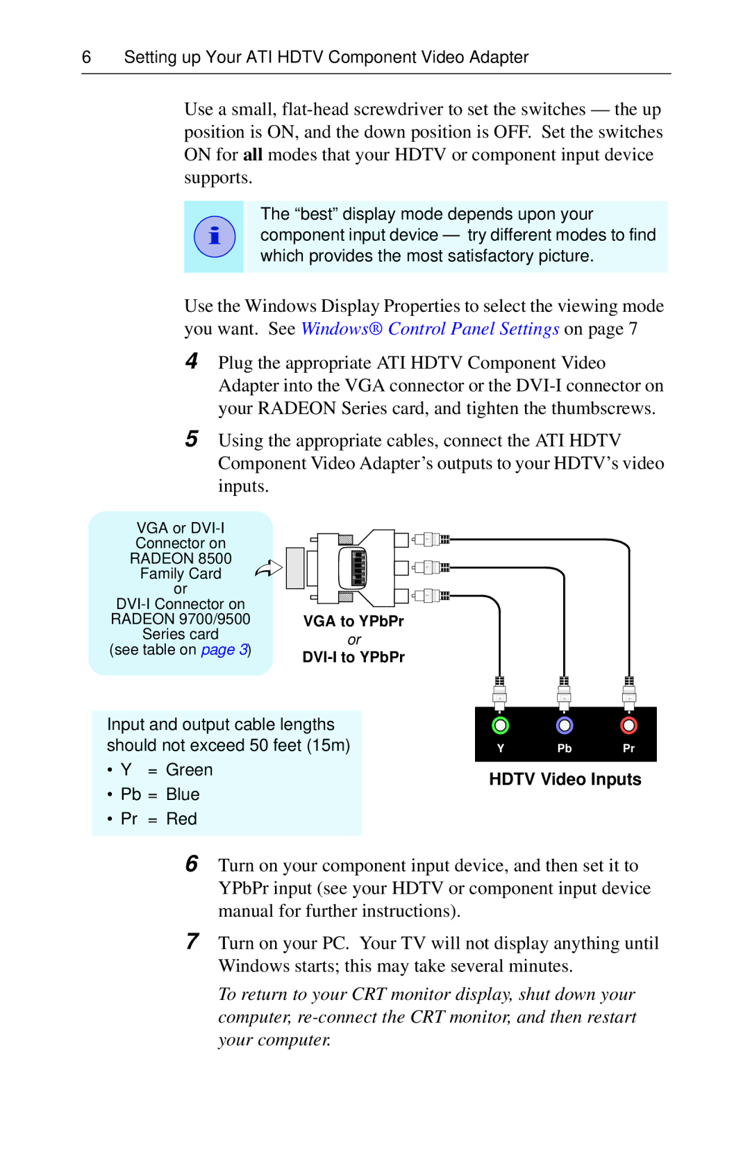
5Using the appropriate cables, connect the ATI HDTV Component Video Adapter’s outputs to your HDTV’s video inputs.
VGA or
Family Card or
(see table on page 3)
EC | 6 |
| 5 |
| 4 |
| 3 |
O | 2 |
| 1 |
VGA to YPbPr
or
Input and output cable lengths should not exceed 50 feet (15m)
•Y = Green
•Pb = Blue
•Pr = Red
Y | Pb | Pr |
HDTV Video Inputs
6Turn on your component input device, and then set it to YPbPr input (see your HDTV or component input device manual for further instructions).
7Turn on your PC. Your TV will not display anything until Windows starts; this may take several minutes.
To return to your CRT monitor display, shut down your computer,