Mounting Location:
Volume controls should be placed in accessible wall locations that are close to entryways, exits, light switches, or telephones. They may also be ganged with other low voltage* controls such as keypads or infrared repeaters.
*Note: WhisperTouch should not be mounted into the same electrical box used for a 110-volt device
—even if the box says it is partitioned for this pur- pose. Speaker wires may pick up electrical noise which will be transmitted as a buzzing or popping sound to the loudspeakers.
Mounting Requirements:
Switched WhisperTouch units are slightly taller, wider, and deeper than most volume controls and requires a 20 cu in. E.O. box with a minimum inside depth of 2.75" and a minimum inside height of 2.985". Recommended boxes for new construc- tion include: Carlon PVC switch box #B-120A, and RACO PVC outlet box. For retrofit applications, CADDY drywall trim ring #MPLS may be used.
Calculating the proper Impedance settings for the system:
WhisperTouch is an impedance-matching stereo vol- ume control that allows multiple loudspeaker pairs and volume controls to be connected, in parallel, without the additional cost of a separate impedance- matching device. For flexibility in system design, WhisperTouch has three impedance matching capa- bilities: 2X, 4X and 8X, as well as a 1X non-imped- ance matching setting that allows the unit to be used as a standard 8 Ohm volume control
To determine which setting should be used (1X, 2X, 4X and 8X) you will need to know the number of loudspeaker pairs, the loudspeaker impedance, and the load capability (output impedance) of the amplifier. Most amplifiers will handle a load down to four or two ohms with some going as low as 1 ohm.
Using the chart on page one; cross reference the number of loudspeaker pairs to the amplifier imped- ance. Notice that the 4X jumper setting will allow twice as many loudspeaker pairs.
Example: If you have 8 pairs of 8-ohm loudspeak- ers and an amplifier capable of handling a 4 ohm load you must set WhisperTouch at the 4X setting for the amplifier to drive all 8 pairs of speakers at full vol- ume. Note that the 2X setting allows only 4 pairs of 8-ohm loudspeakers to operate on a 4 ohm load. If however, you could select an amplifier with a 2 ohm output impedance, the same 8 loudspeakers could operate on a 2 ohm load (at the 2X setting) or 16 loudspeaker pairs (at the 4X setting). Whenever pos- sible, the lowest jumper setting for a given amplifier should be selected.
Changing Impedance Jumpers:
Once the proper impedance setting is determined, locate the impedance jumpers (black plastic mod- ules) on the back side of the circuit board. One jumper is for the right channel, the other for the left. Next, locate the 1X, 2X, 4X and 8X settings on the circuit board for each channel. If the settings are correct, continue to the next step. If the settings need to change, simply slide the jumper modules off and reinstall them on to the correct two pins.
Limitations:
WhisperTouch limits the degree of impedance match- ing to eight times so that music quality and overall performance is not sacrificed. We do not recommend that any quality, multi-room music system be con- nected to a device which provides 16X impedance matching as it may limit the amplifier’s power and system performance.
Prewiring and Installation:
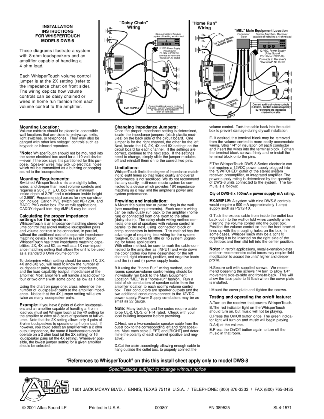
A.Mount the outlet box or plaster ring in the wall (see mounting requirements). Each room’s wiring can be individually run back to the amplifier (home run) or connected from one room to the other (daisy chain). The daisy chain wiring method con- nects one set of speakers with volume control in parallel to the next, using connection block or crimp connectors in between. This method has the advantage of requiring less wiring for the system rough-in, but allows for little or no system upgrad- ing for future applications.
With either method, be sure to mark the cable con- nected to the amplifier as [INPUT] and write down the color codes you have designated for the left channel, right channel, positive, and negative leads and the (+) and (-) power supply leads.
B.If using the "Home Run" wiring method, each rooms speaker/volume control wiring should be individually run back to the Main Equipment Location "MEL" in a "home-run" fashion. Run a total of six conductors of speaker cable from the amplifier location to each room's volume control box. Four conductors are speaker outputs and the two additional conductors connect to the 12VDC power supply. Power Supply conductors may be as small as 22 gauge.
Note: Many building and fire codes require cable to be CL-2, CL-3, or FT4 rated. Check with your local building inspector before prewiring.
C.Next, run a two-conductor speaker cable from the outlet box to the corresponding left and right speak- ers. Mark each cable [LEFT] and [RIGHT] and deter- mine the polarity of each channel (positive and neg- ative).
D.Cut the cable accordingly, allowing enough cable to hang outside the outlet box, to properly connect the
volume control. Tuck the cable back into the outlet box to prevent damage during drywall installation.
E. If desired, the terminal block may be removed from the volume control to more easily accomodate wiring. Strip 1/4" of insulation off each conductor and insert the wires into the terminal block. Tighten the terminal block screws frimly and re-install the terminal block onto the pins.
F.The WhisperTouch DWS-8 Series electronic con- trol requires a 12VDC power supply plugged into the “SWITCHED” outlet of the stereo system receiver, preamplifier, or integrated amplifier. The power supply rating is determined by the quantity of DWS-8 units connected to the system. The for- mula is a follows:
Qty of DWS-8 x 100mA = power supply mA rating.
EXAMPLE: A system with nine DWS-8 controls would require a 900 mA (approximately 1 amp) supply such as PS12-10.
G.Tuck the excess cable from inside the outlet box back out into the wall or fold wires carefully while inserting the volume control into the outlet box. Position the volume control so that the front bracket lines up with the mounting holes on the box. In some cases, WhisperTouch may be a tight fit requiring it to be inserted on the right side of the outlet box and then slid left into the center position.
Note: In retrofit applications, metal extension plates and non-recommended outlet boxes may require field modification to accept the units’ higher and deeper profile.
H.Secure unit with supplied screws. We recom- mend loosening the screws 1/4 turn to allow 1/4" movement side-to-side and front-to-back. This will allow the face plate to fit flush when the cover plate is installed.
I.Mount the cover plate and tighten the screws.
Testing and operating the on/off feature:
A.Turn on the receiver that powers WhisperTouch.
B.The red indicator light on the WhisperTouch should turn on, but music will not be playing.
C.Press the On/Off button once. The green indica- tor light will turn on and music will begin playing.
D.Adjust the volume.
E.Press the On/Off button again to turn off the music in that room.