Panel Description
1
HDMI OUT
ETHERNET |
2 |
| 3 |
IR | - | + |
IR IN | IR OUT | |
TX RX
RS232 |
![]() PWR
PWR
![]() LINK
LINK ![]()
![]() FW
FW
4
5
6
7
8
9
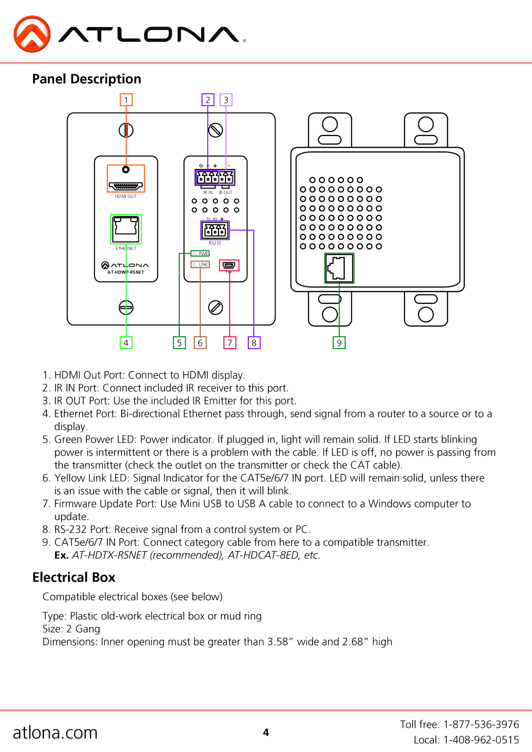
1.HDMI Out Port: Connect to HDMI display.
2.IR IN Port: Connect included IR receiver to this port.
3.IR OUT Port: Use the included IR Emitter for this port.
4.Ethernet Port:
5.Green Power LED: Power indicator. If plugged in, light will remain solid. If LED starts blinking power is intermittent or there is a problem with the cable. If LED is off, no power is passing from the transmitter (check the outlet on the transmitter or check the CAT cable).
6.Yellow Link LED: Signal Indicator for the CAT5e/6/7 IN port. LED will remain solid, unless there is an issue with the cable or signal, then it will blink.
7.Firmware Update Port: Use Mini USB to USB A cable to connect to a Windows computer to update.
8.
9.CAT5e/6/7 IN Port: Connect category cable from here to a compatible transmitter. Ex.
Electrical Box
Compatible electrical boxes (see below)
Type: Plastic
Size: 2 Gang
Dimensions: Inner opening must be greater than 3.58” wide and 2.68” high
atlona.com | 4 | Toll free: |
Local: | ||
|
|