CT240 Telephone
Controller
I n s tal l ati o n I n s tru c ti o n s an d U s e r M an u al
1 . I ntroduction
The CT240 telephone controller is designed to remotely control your home’s thermostat. It is possible to command a temperature decrease (Unoccupied) during a prolonged absence or a temperature increase (Comfort) before you return home.
Depending on your thermostat’s operating characteristics, it either connects to the Aube output (for most Aube models) or to the auxil- iary output.
When the auxiliary output is not used to control a thermostat, it can be used to simultaneously control a load such as a water heater, lighting, etc.
1Power Indicator. Indicates the CT240 is powered on. To turn it off, unplug the power transformer.
2Communication Indicator. Indicates the CT240 has answered and is awaiting a command.
3Ring Indicator. This indicator flashes when the phone rings.
4Reset. This button can be used to reset the CT240 to its default values. See section 3.3.
5Manual Output Activation Button. Can be used to manually switch the relay status.
6Auxiliary Output. See section 2.
712 VDC Output. See section 2.
2.I nstallation
Any device connected to a telephone line must conform to the coun- try's standards. The CT240 telephone controller meets:
•FCC68 standards for installation on the North American network.
•FDTBR21 standards for installation on the European network.
2.1 Included Parts
•One CT240 telephone controller
•One power transformer 120 V (North America) or 250 V (Europe)
•One 5 m (16 foot) telephone cable
NOTE: If you are using an answering machine, position the answer- ing machine switch to ON before installing the CT240.
Make sure that your answering machine answers after a minimum of 4 rings.
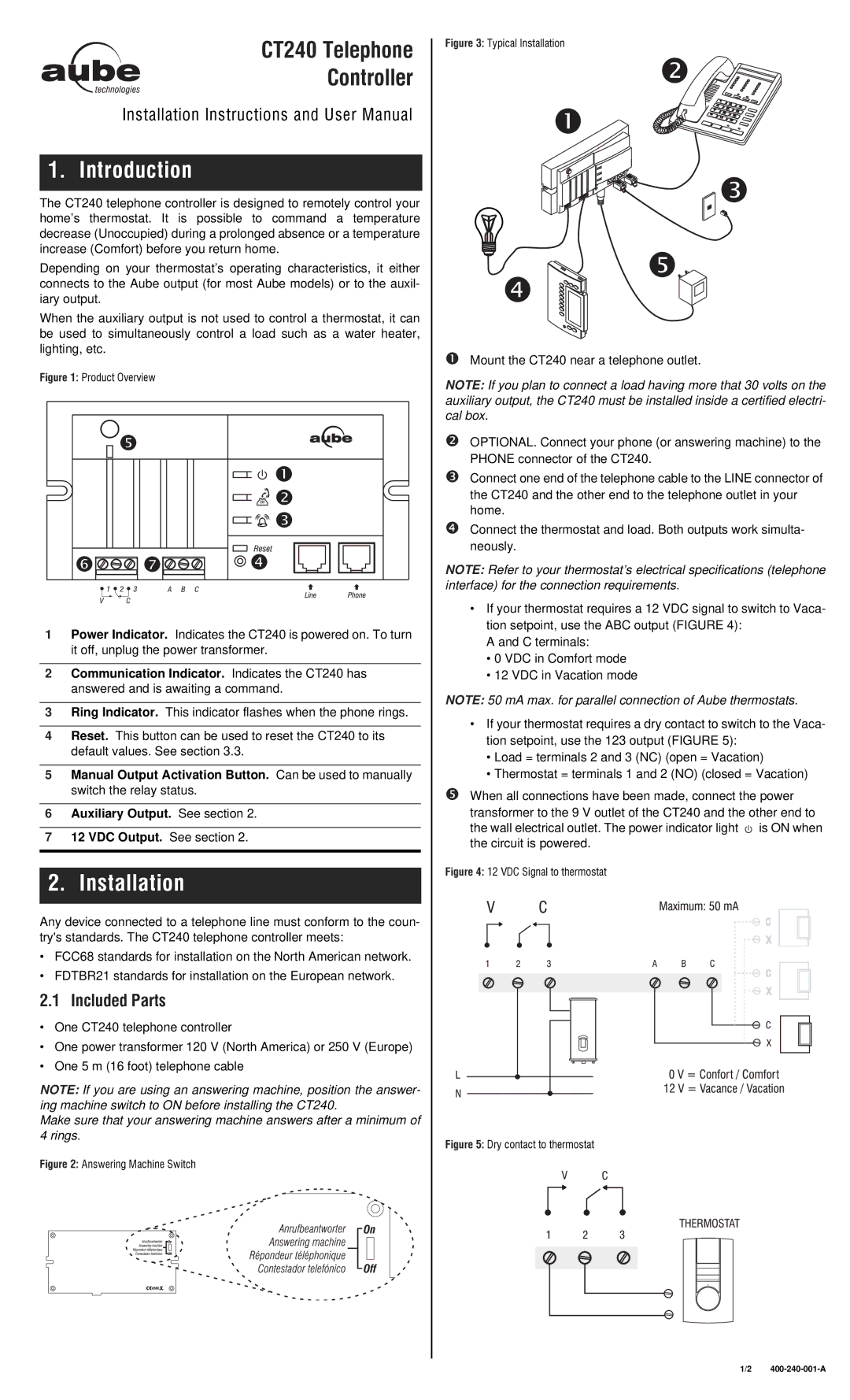
nMount the CT240 near a telephone outlet.
NOTE: If you plan to connect a load having more that 30 volts on the auxiliary output, the CT240 must be installed inside a certified electri- cal box.
oOPTIONAL. Connect your phone (or answering machine) to the PHONE connector of the CT240.
pConnect one end of the telephone cable to the LINE connector of the CT240 and the other end to the telephone outlet in your home.
qConnect the thermostat and load. Both outputs work simulta- neously.
NOTE: Refer to your thermostat’s electrical specifications (telephone interface) for the connection requirements.
•If your thermostat requires a 12 VDC signal to switch to Vaca- tion setpoint, use the ABC output (FIGURE 4):
A and C terminals:
•0 VDC in Comfort mode
•12 VDC in Vacation mode
NOTE: 50 mA max. for parallel connection of Aube thermostats.
•If your thermostat requires a dry contact to switch to the Vaca- tion setpoint, use the 123 output (FIGURE 5):
•Load = terminals 2 and 3 (NC) (open = Vacation)
•Thermostat = terminals 1 and 2 (NO) (closed = Vacation)
rWhen all connections have been made, connect the power transformer to the 9 V outlet of the CT240 and the other end to the wall electrical outlet. The power indicator light ![]() is ON when the circuit is powered.
is ON when the circuit is powered.
1/2