The Audio-Technica ATW-49SP Active Antenna Splitter Kit includes two one-input, two-output Active Antenna Splitters designed for use with Audio-Technica 4000 and 5000 Series UHF wireless receivers and ATW-A49 LPDA antennas.* Each Active Antenna Splitter is a broadband device (frequency range from 440 to 900 MHz) that splits an incoming RF signal into two identical outgoing RF signals. One set of Active Antenna Splitters enables one set of antennas to feed wireless receivers of different frequency bands. To compensate for RF signal loss associated with signal splitting, the Active Antenna Splitter provides unity gain: there is no RF signal loss from the original antenna signal.
Each kit includes: two Active Antenna Splitters, four 18" BNC-to-BNC RG 58 coaxial antenna cables, and two BNC-to-BNC barrel adapters.
NOTE: The ATW-49SP Antenna Splitter requires +12V DC power from any Audio-Technica 4000 or 5000 series receiver or +5 to +14V DC from any wireless receiver or antenna distribution system that offers antenna power. At least one of the receiver's or distribution amplifier's antenna terminals must provide this voltage source. A light on each Active Antenna Splitter indicates that power has been correctly applied.
*The ATW-49SP Active Antenna Splitter Kit is also suitable for use with other receivers that are in its specified band, use BNC antenna connectors, and provide antenna terminal voltage; it may also be used with a variety of other antennas from Audio-Technica and other manufacturers.
HOW TO INSTALL THE ATW-49SP ACTIVE ANTENNA SPLITTERS
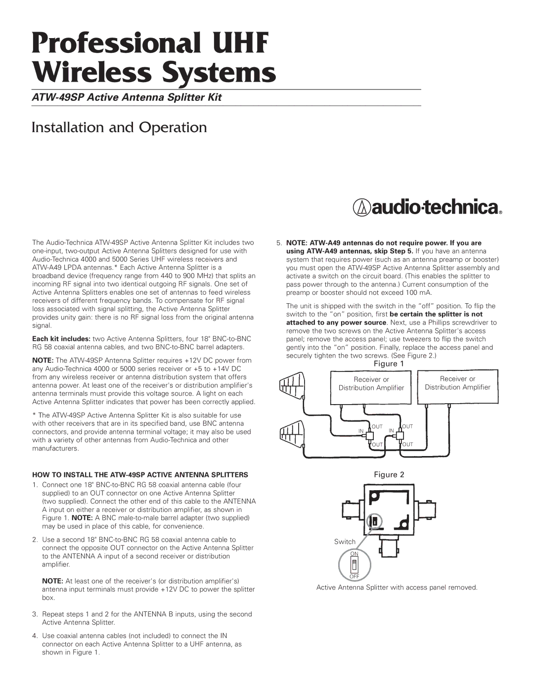
1.Connect one 18" BNC-to-BNC RG 58 coaxial antenna cable (four supplied) to an OUT connector on one Active Antenna Splitter (two supplied). Connect the other end of this cable to the ANTENNA A input on either a receiver or distribution amplifier, as shown in Figure 1. NOTE: A BNC male-to-male barrel adapter (two supplied) may be used in place of this cable, for convenience.
2.Use a second 18" BNC-to-BNC RG 58 coaxial antenna cable to connect the opposite OUT connector on the Active Antenna Splitter to the ANTENNA A input of a second receiver or distribution amplifier.
NOTE: At least one of the receiver's (or distribution amplifier's) antenna input terminals must provide +12V DC to power the splitter box.
3.Repeat steps 1 and 2 for the ANTENNA B inputs, using the second Active Antenna Splitter.
4.Use coaxial antenna cables (not included) to connect the IN connector on each Active Antenna Splitter to a UHF antenna, as shown in Figure 1.
5.NOTE: ATW-A49 antennas do not require power. If you are using ATW-A49 antennas, skip Step 5. If you have an antenna system that requires power (such as an antenna preamp or booster) you must open the ATW-49SP Active Antenna Splitter assembly and activate a switch on the circuit board. (This enables the splitter to pass power through to the antenna.) Current consumption of the preamp or booster should not exceed 100 mA.
The unit is shipped with the switch in the “off” position. To flip the switch to the “on” position, first be certain the splitter is not attached to any power source. Next, use a Phillips screwdriver to remove the two screws on the Active Antenna Splitter's access panel; remove the access panel; use tweezers to flip the switch gently into the “on” position. Finally, replace the access panel and securely tighten the two screws. (See Figure 2.)
Figure 1
Receiver or | Receiver or |
Distribution Amplifier | Distribution Amplifier |
OUT OUT
IN IN
OUT OUT
Figure 2
Switch
ON
OFF
Active Antenna Splitter with access panel removed.