Audio-Technica ATW-A62P, ATW-A72P manual Introduction, Antenna Location & Orientation, Fig. A

Models: ATW-A72P

1 4
Download 4 pages 40.99 Kb
Page 2
Image 2
UHF Powered Dipole Antennas

UHF Powered Dipole Antennas

Installation and Operation

Warning: To prevent fire or shock hazard, do not expose this appliance to rain or moisture. Attention: Pour prévenir feu ou choc électrique, ne pas exposé l’appareil à la pluie ou à l’humidité.

CAUTION! The circuits and wiring inside the antennas are adjusted for optimum performance. Do not attempt to alter circuitry or wiring to affect output. To do so will void the warranty and may cause improper operation or system degradation.

This device complies with part 15 of the FCC Rules. Operation is subject to the condition that this device does not cause harmful interference.

This device complies with INDUSTRY CANADA R.S.S. 210, en conformité avec IC: RSS-210/CNR210. Operation is subject to the following conditions: 1) This device may not cause harmful interference and 2) this device must accept any interference received, including interference which may cause undesired operation.

CAUTION! To prevent electrical shock and possible damage to the antenna, use caution when connecting 12V power from the receiver or antenna distribution system.

Introduction

Antenna Location & Orientation

Audio-Technica ATW-A62P and ATW-A72P powered dipole antennas provide effective and reliable signal pickup for UHF wireless systems. Supplied in pairs, these antennas are intend- ed to improve performance of diversity wireless receiving systems with dual antenna inputs.

Designed for temporary or permanent installation, these anten- nas are powered by 12 volts DC provided on the antenna cable by the associated receiver or antenna distribution system.

Power is required for antenna operation; an indicator on each housing lights when power is applied. An internal gain-setting switch permits selection of +10, +4 or –2 dB operation, to compensate for cable losses or other operating conditions.

The ATW-A62P and ATW-A72P are designed for particular UHF frequency bands:

ATW-A62P: 656-668 MHz (TV channels 45-47)

ATW-A72P: 728-740 MHz (TV channels 57-59)

The ATW-A62P and ATW-A72P are designed for interior use. Do not install them outdoors, or where condensation or extremely high humidity is present. Both models permit several means of mounting for temporary use or permanent installation.

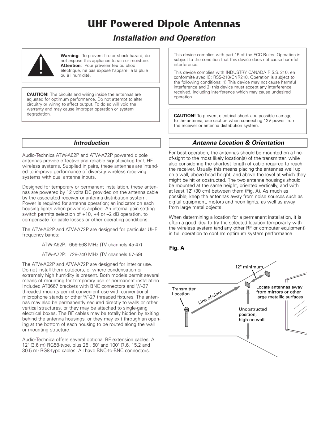
For best operation, the antennas should be mounted on a line- of-sight to the most likely location(s) of the transmitter, while also considering the shortest length of cable required to reach the receiver. Usually this means placing the antennas well up on a wall, above head height, and above the level at which they might be hit or obstructed. The two antenna housings should be mounted at the same height, oriented vertically, and with at least 12" (30 cm) between them (Fig. A). As much as possible, keep the antennas away from noise sources such as digital equipment, motors and neon lights, as well as away from large metal objects.

When determining a location for a permanent installation, it is often a good idea to try the selected location temporarily with the wireless system (and any other RF or computer equipment) in full operation to confirm optimum system performance.

Fig. A

12" minimum

Included AT8667 brackets with BNC connectors and 5/8"-27 threaded mounts permit convenient use with conventional microphone stands or other 5/8"-27 threaded fixtures. The anten- nas may also be permanently secured directly to walls or other vertical structures, or they may be attached to single-gang electrical boxes. The RF cables may be totally hidden by exiting behind the antenna housings, or they may exit through an open- ing at the bottom of each housing to be routed along the wall or mounting structure.

Audio-Technica offers several optional RF extension cables: A 12' (3.6 m) RG58-type, plus 25', 50' and 100' (7.6, 15.2 and 30.5 m) RG8-type cables. All have BNC-to-BNC connectors.

Transmitter Location

Locate antennas away from mirrors or other large metallic surfaces

Unobstructed position, high on wall

Page 2
Image 2
Audio-Technica ATW-A62P, ATW-A72P manual Introduction, Antenna Location & Orientation, Fig. A, UHF Powered Dipole Antennas