Cable Connections
Refer to Figure F (cable rear exit) or Figure G (bottom exit) for connecting positions. When using a screwdriver on the antenna terminals, always support the PC board.
Center Conductor: Wrap the center conductor(s) clockwise around its screw and tighten snugly. (If using RG8, it is good practice to bend its center conductors using pliers, not force them around the screw terminal.)
Shield: It’s most effective to remove the cable clamp entirely, properly position the shield portion of the cable, and then care- fully reinstall the cable clamp over the shield. Make certain that the shield (and cable) are firmly clamped, and that no shield wires are loose or touching the center conductor.
Especially when using RG8 or other large, stiff cable, it’s a good idea to provide some form of clamping of the cable near the antenna’s cable entrance for strain relief.
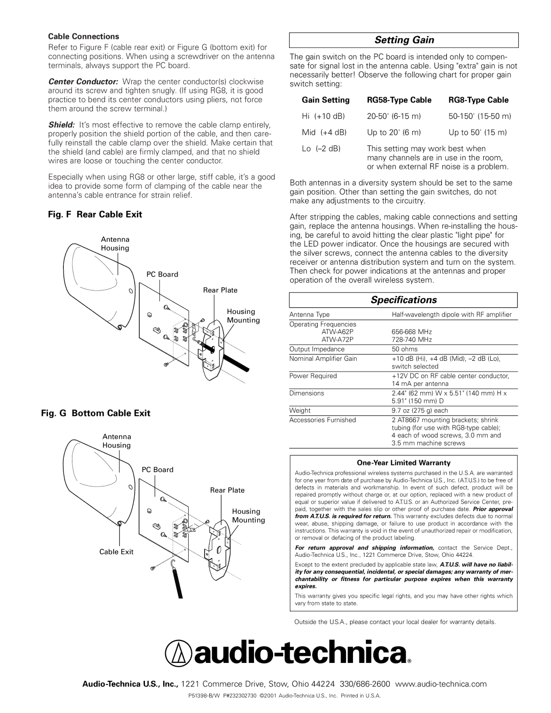
Fig. F Rear Cable Exit
Antenna
Housing
PC Board
Rear Plate
Housing
Mounting
Fig. G Bottom Cable Exit
Antenna
Housing
PC Board
Rear Plate
Housing
Mounting
Cable Exit
Setting Gain
The gain switch on the PC board is intended only to compen- sate for signal lost in the antenna cable. Using "extra" gain is not necessarily better! Observe the following chart for proper gain switch setting:
Gain Setting |
|
| |
Hi (+10 dB) | |||
Mid | (+4 dB) | Up to 20' (6 m) | Up to 50' (15 m) |
Lo | This setting may work best when | ||
|
| many channels are in use in the room, | |
|
| or when external RF noise is a problem. | |
Both antennas in a diversity system should be set to the same gain position. Other than setting the gain switches, do not make any adjustments to the circuitry.
After stripping the cables, making cable connections and setting gain, replace the antenna housings. When
| Specifications |
|
|
Antenna Type | |
Operating Frequencies |
|
| |
Output Impedance | 50 ohms |
Nominal Amplifier Gain | +10 dB (Hi), +4 dB (Mid), |
| switch selected |
Power Required | +12V DC on RF cable center conductor, |
| 14 mA per antenna |
|
|
Dimensions | 2.44" (62 mm) W x 5.51" (140 mm) H x |
| 5.91" (150 mm) D |
Weight | 9.7 oz (275 g) each |
Accessories Furnished | 2 AT8667 mounting brackets; shrink |
| tubing (for use with |
| 4 each of wood screws, 3.0 mm and |
| 3.5 mm machine screws |
|
|
One-Year Limited Warranty
For return approval and shipping information, contact the Service Dept.,
Except to the extent precluded by applicable state law, A.T.U.S. will have no liabil- ity for any consequential, incidental, or special damages; any warranty of mer- chantability or fitness for particular purpose expires when this warranty expires.
This warranty gives you specific legal rights, and you may have other rights which vary from state to state.
Outside the U.S.A., please contact your local dealer for warranty details.