hole and is less likely to damage the table surface.)
5.Using a 1.5 mm (1/16") drill bit, drill three pilot holes for the mounting screws. (If mounting below the table surface, be certain NOT to drill pilot holes through the table.)
6.Place the AT8474 mount over the hole and partially tighten the three screws. Then place the microphone in the AT8474 so that the microphone’s power module (base) extends through the AT8474 mount into the hole. Tighten all three screws evenly. For maximum security, the screws should be tight enough to ensure that the microphone is held securely in place and cannot be removed without loosening
the screws.
7.If mounting the AT8474 mount below the surface of the table, slide the rubber trim ring over the microphone (above the table surface) and seat it between the microphone and the sides of the hole for a
finished appearance. (If mounting the AT8474 above the surface of the table, you may also choose to use the trim ring beneath the surface of the table, for added attenuation of noise, shock and vibration.)
8.After installing the microphone, assure maximum shock mount effectiveness by providing some slack in the connecting cable. The cable can be secured to the table with a standard wire clip or cable tie (not included).
Architect’s and Engineer’s Specifications
The microphone shall be a fixed-charge condenser designed for permanent installation or portable applications. It shall have a cardioid polar pattern with a uniform 120° angle of acceptance and a frequency response of 30 Hz to 20,000 Hz. It shall be capable of accepting optional interchangeable elements for additional polar patterns. The microphone shall operate from an external 11V to 52V DC phantom power source. It shall be capable of handling sound input levels up to 138 dB with a dynamic range of 109 dB. Nominal open-circuit output voltage shall be 10.0 mV at 1 V, 1 Pascal. Output shall be low impedance balanced (250 ohms). It shall offer outstanding rejection of radio frequency interference (RFI).
The microphone shall incorporate a self-contained power module with an XLRM-type connector at the base for direct connection to a mating XLRF- type panel jack or cable connector. It shall include a recessed switch to permit choice of flat response or 80 Hz low-frequency roll-off. The microphone shall incorporate an illuminating mute switch in the power module.
The mute switch shall illuminate when the microphone is on. The mute switch shall be quiet in operation with no mechanical clicks or pops and shall always return to the off position (after momentarily turning on to verify microphone connection) when phantom power is restored.
A universal isolation-type shock mount suitable for above or below surface installation shall be supplied for mounting the microphone in a solid surface. It shall be possible to firmly secure the microphone in the mount. The mount shall include appropriate hardware for installation. For alternative mounting and portable applications, the microphone shall be supplied with a stand clamp to permit attaching the microphone directly to a standard 5/8"- 27 or 3/8"-16 thread. A two-stage foam windscreen shall also be included.
The microphone shall be a small-diameter double gooseneck design, with an overall length of [304.8 mm (12.00"): ES915SC12]; [381.0 mm (15.00"): ES915SC15]; [457.2 mm (18.00"): ES915SC18]; [533.4 mm (21.00"): ES915SC21] [609.6 mm (24.00"): ES915SC24] and a head diameter of 8.4 mm (0.33"). Weight shall be [125 grams (4.4 oz): ES915SC12]; [130 grams (4.6 oz): ES915SC15]; [135 grams (4.8 oz): ES915SC18]; [140 grams (4.9 oz): ES915SC21]; [145 grams (5.1 oz): ES915SC24]. Finish shall be low-reflectance black.
The Audio-Technica [ES915SC12]; [ES915SC15]; [ES915SC18]; [ES915SC21]; [ES915SC24] is specified.
Specifications | |
| |
Element | Fixed-charge back plate, permanently |
| polarized condenser |
Polar pattern | Cardioid |
Frequency response | 30-20,000 Hz |
Low frequency roll-off | 80 Hz, 18 dB/octave |
Open circuit sensitivity | –40 dB (10.0 mV) re 1V at 1 Pa |
Impedance | 250 ohms |
Maximum input sound level | 138 dB SPL, 1 kHz at 1% T.H.D. |
Dynamic range (typical) | 109 dB, 1 kHz at Max SPL |
Signal-to-noise ratio1 | 65 dB, 1 kHz at 1 Pa |
Phantom power requirements | 11-52V DC, 4 mA typical |
Switches | Flat, roll-off; mute/on |
Weight | ES915SC12: 125 g (4.4 oz) |
| ES915SC15: 130 g (4.6 oz) |
| ES915SC18: 135 g (4.8 oz) |
| ES915SC21: 140 g (4.9 oz) |
| ES915SC24: 145 g (5.1 oz) |
Dimensions | ES915SC12: 304.8 mm (12.00") long |
| ES915SC15: 381.0 mm (15.00") long |
| ES915SC18: 457.2 mm (18.00") long |
| ES915SC21: 533.4 mm (21.00") long |
| ES915SC24: 609.6 mm (24.00") long, |
| All: 8.4 mm (0.33") head diameter, |
| 18.9 mm (0.74") base diameter |
Output connector | Integral 3-pin XLRM-type |
Optional interchangeable elements | ESE-O omnidirectional (360°) |
| ESE-H hypercardioid (100°) |
| ESE-ML MicroLine® (90°) |
Audio-Technica case style | M26 |
Accessories furnished | AT8474 universal isolation mount; AT8473 |
| quick-mount stand adapter; 5/8"-27 to 3/8"-16 |
| threaded adapter; AT8109 two-stage foam |
| windscreen |
| |
In the interest of standards development, A.T.U.S. offers full details on its test methods to other industry professionals on request.
1 Pascal = 10 dynes/cm2 = 10 microbars = 94 dB SPL
1Typical, A-weighted, using Audio Precision System One. Specifications are subject to change without notice.
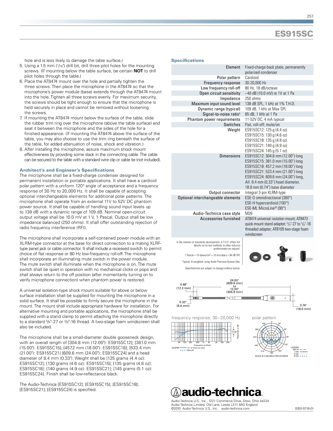
| | 24.00" |
| 0.48" | (609.6 mm) |
| to |
| (12.3 mm) |
| 12.00" |
| | (304.8 mm) |
0.33"
(8.4 mm)0.74"
(18.9 mm)
frequency response: 30–20,000 Hz | polar pattern |
| | | | | | | | | | 330˚ | 0˚ | |
| | | | | | | | | in dB | 30˚ | |
| | | | | | | | | 300˚ | 60˚ | |
| | | | | | | | | Response | |
| | | | | | | | 10 dB | 270˚ | 90˚ | |
50 | 100 | 200 | 500 | 1k | 2k | 5k | 10k | 20k | | | 120˚ | |
| | | Frequency in Hertz | | | | | 240˚ | |
| | | | | | | | LEGEND |
LEGEND | | 12" or more on axis | | | | | | | |
| | Roll-off | | | | | | | | 210˚ | 150˚ | 200 Hz |
| | | | | | | | | 1 kHz |
| | | | | | | | | | | 180˚ |
| | | | | | | | | | | 5 kHz |
| | | | | | | | | | SCALE IS 5 DECIBELS PER DIVISION |
| | | | | | | | | | 8 kHz |