DESCRIPTIONS AND FUNCTIONS
1 | 2 | 3 | 4 |
| 5 | 6 | 7 | 8 | 9 | 31 |
| 32 |
| 33 | |
10 | 11 12 13 | 14 | 15 | 16 | 17 | 18 | 19 |
|
|
|
|
|
| ||
|
|
|
|
|
|
|
|
|
|
|
|
| |||
|
|
|
|
|
|
|
|
| AKJ7002 |
|
|
|
|
|
|
|
|
|
|
|
|
|
| Professional Karaoke |
|
| b |
| # |
| |
|
|
|
|
|
|
|
| Mixing Amplifier |
|
|
|
|
|
| |
|
|
|
|
|
|
|
| with Digital Echo |
|
|
|
|
|
| |
|
|
|
|
|
|
|
| & Key Controls |
| INPUT A | DOWN | NATURAL | UP | INPUT B | |
|
|
|
|
|
|
|
|
|
|
| |||||
| 20 |
|
| 21 | 22 | 23 | 24 | 25 | 34 | 35 | 36 |
|
|
| 37 |
|
|
| 26 |
| 27 | 28 | 29 | 30 |
|
|
|
| 38 |
|
|
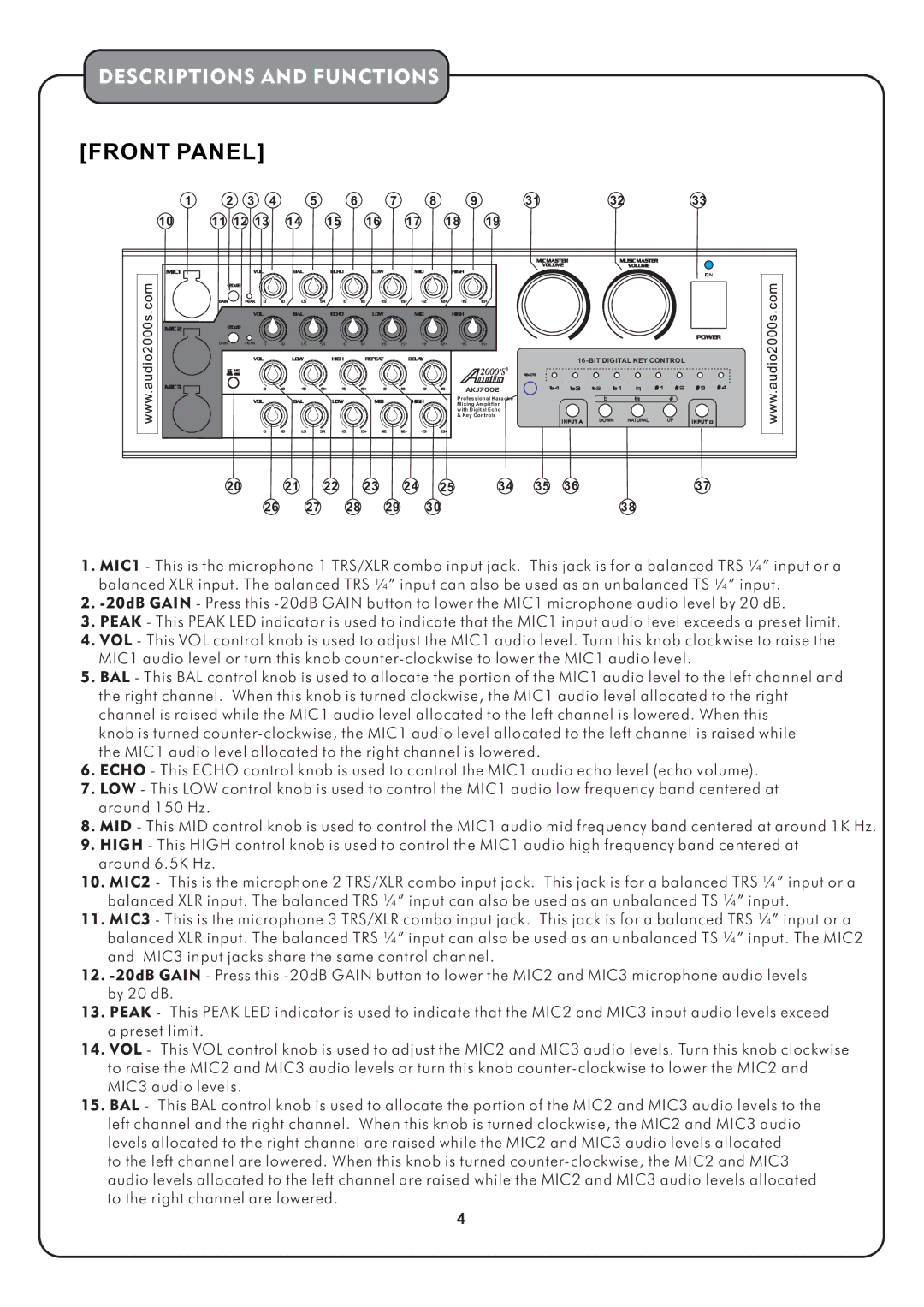
1.MIC1 - This is the microphone 1 TRS/XLR combo input jack. This jack is for a balanced TRS ¼” input or a balanced XLR input. The balanced TRS ¼” input can also be used as an unbalanced TS ¼” input.
2.
3.PEAK - This PEAK LED indicator is used to indicate that the MIC1 input audio level exceeds a preset limit.
4.VOL - This VOL control knob is used to adjust the MIC1 audio level. Turn this knob clockwise to raise the MIC1 audio level or turn this knob
5.BAL - This BAL control knob is used to allocate the portion of the MIC1 audio level to the left channel and the right channel. When this knob is turned clockwise, the MIC1 audio level allocated to the right channel is raised while the MIC1 audio level allocated to the left channel is lowered. When this
knob is turned
6.ECHO - This ECHO control knob is used to control the MIC1 audio echo level (echo volume).
7.LOW - This LOW control knob is used to control the MIC1 audio low frequency band centered at around 150 Hz.
8.MID - This MID control knob is used to control the MIC1 audio mid frequency band centered at around 1K Hz.
9.HIGH - This HIGH control knob is used to control the MIC1 audio high frequency band centered at around 6.5K Hz.
10.MIC2 - This is the microphone 2 TRS/XLR combo input jack. This jack is for a balanced TRS ¼” input or a balanced XLR input. The balanced TRS ¼” input can also be used as an unbalanced TS ¼” input.
11.MIC3 - This is the microphone 3 TRS/XLR combo input jack. This jack is for a balanced TRS ¼” input or a
balanced XLR input. The balanced TRS ¼” input can also be used as an unbalanced TS ¼” input. The MIC2 and MIC3 input jacks share the same control channel.
12.
by 20 dB.
13.PEAK - This PEAK LED indicator is used to indicate that the MIC2 and MIC3 input audio levels exceed a preset limit.
14.VOL - This VOL control knob is used to adjust the MIC2 and MIC3 audio levels. Turn this knob clockwise
to raise the MIC2 and MIC3 audio levels or turn this knob
15.BAL - This BAL control knob is used to allocate the portion of the MIC2 and MIC3 audio levels to the
left channel and the right channel. When this knob is turned clockwise, the MIC2 and MIC3 audio levels allocated to the right channel are raised while the MIC2 and MIC3 audio levels allocated to the left channel are lowered. When this knob is turned
4