Identification of Controls (continued)
Main unit (rear view)
SPEAKER
R
SPEAKER
L
1 | 1 |
S/PDIF | HDMI1 | HDMI2 | COMPONENT INPUT 1 |
| COMPONENT INPUT 2 |
|
|
|
| R AUDIO | L | R AUDIO | L |
2 | 3 | 4 | 5 | 6 | 7 | 8 | 9 | 10 11 | 12 | 13 | 14 | 15 |
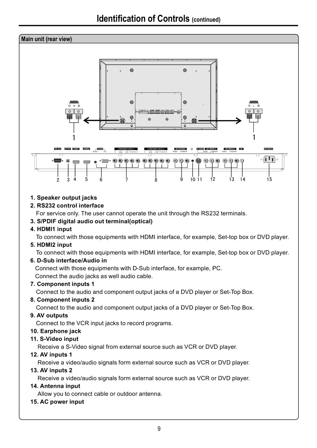
1.Speaker output jacks
2.RS232 control interface
For service only. The user cannot operate the unit through the RS232 terminals.
3.S/PDIF digital audio out terminal(optical)
4.HDMI1 input
To connect with those equipments with HDMI interface, for example,
5. HDMI2 input
To connect with those equipments with HDMI interface, for example,
6. D-Sub interface/Audio in
Connect with those equipments with
Connect the audio jacks as well audio cable.
7. Component inputs 1
Connect to the audio and component output jacks of a DVD player or
8. Component inputs 2
Connect to the audio and component output jacks of a DVD player or
9. AV outputs
Connect to the VCR input jacks to record programs.
10.Earphone jack
11.
Receive a
12. AV inputs 1
Receive a video/audio signals form external source such as VCR or DVD player.
13. AV inputs 2
Receive a video/audio signals form external source such as VCR or DVD player.
14. Antenna input
Allow you to connect cable or outdoor antenna.
15. AC power input
9