WIRING DIAGRAM
Dome Light Harness
Violet/Brown
(Lamp Auto)
Red/Black
(Lamp On)
Black/Red
(Lamp Common)
AV Input Cable | Line |
Line In-R (Red)
Line In-L (White)
Red: +12VDC Accessory Ckt. (Install 5A inline Fuse)
Power Harness | Black: Ground |
AV Output Cable
![]() Line
Line
![]() Line
Line
![]() Line
Line
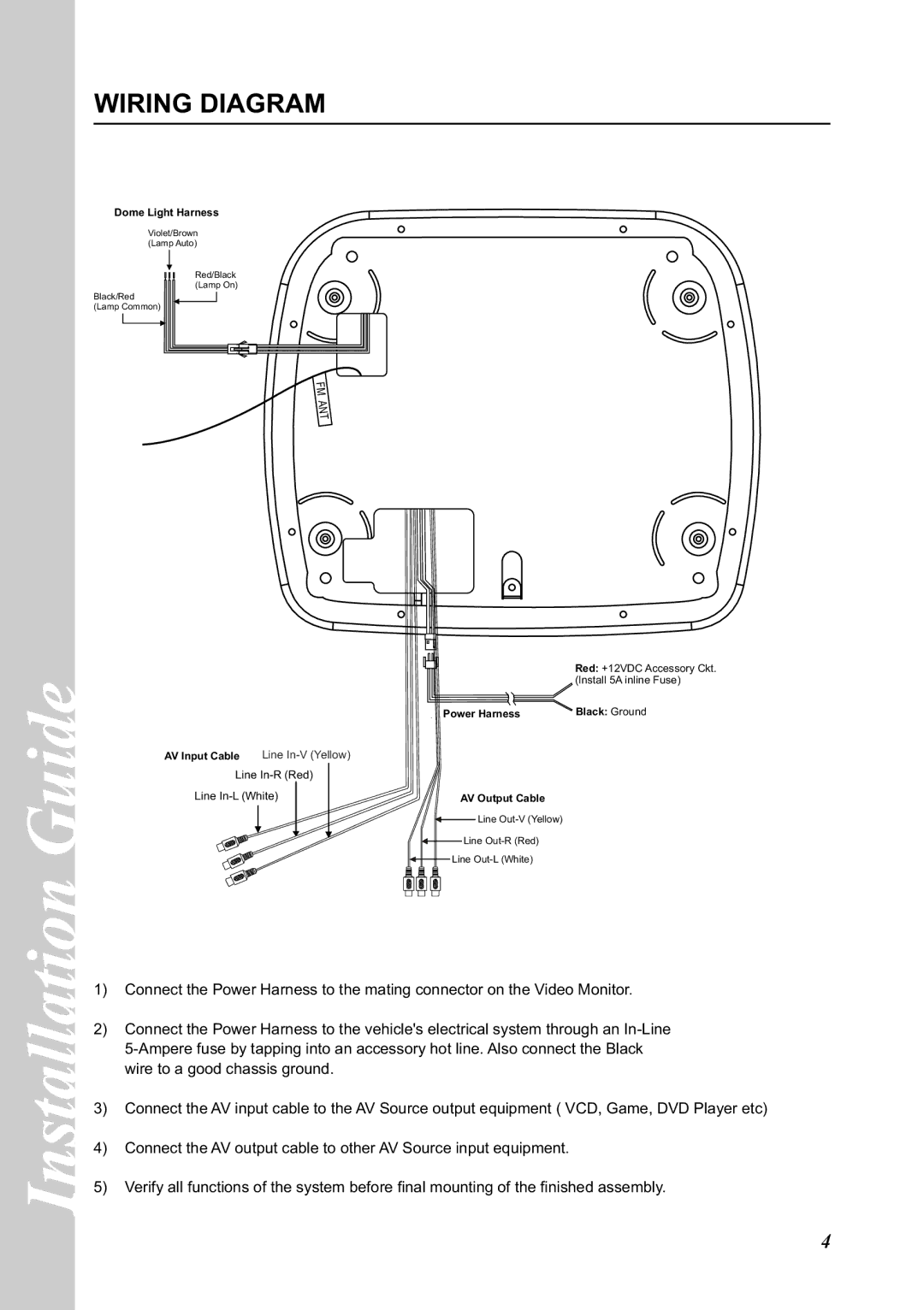
1)Connect the Power Harness to the mating connector on the Video Monitor.
2)Connect the Power Harness to the vehicle's electrical system through an
3)Connect the AV input cable to the AV Source output equipment ( VCD, Game, DVD Player etc)
4)Connect the AV output cable to other AV Source input equipment.
5)Verify all functions of the system before final mounting of the finished assembly.
4
