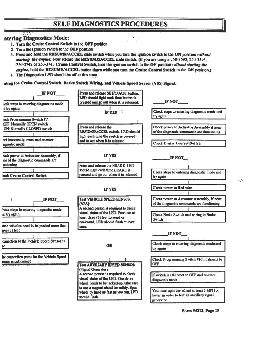
SELF DIAGNOSTICS PROCEDURES
,:~:~:~,';
otering'Diagnostics Mode:
I.Turn the Cnlile Control Switch to the OFF position
2. Turn the ignition switch to the OFF position
3. PressaDd hold the USUME/ACCEL slide switch wbile you turn the ignition switch to the ON position without
bIrD tbc ignition switch to the ON position wit1loll' starting the | ||
button... | wbileyCMlturn the Cnlile Control Switch to the ON position.) | |
4. The Diagnostics LED should be off at this ~
!ltiag the Cnlile Control Switch, Brake Swid Wlri8c. ud Vehkie Speed SeDsor (VSS) Signal:
|
|
| NOT- |
| Pre8881MireIc8IeSET/COASTbutton. | |||||
~ | = | t,..=t=~: | :i;.=;... | =::;A | I | LED ~ | IiIbt e8:h tiDIe00tt00is | |||
~:r | ; | to entering~cs |
| mode | I | prc8IedIIMI | u | whenit is released. | ||
d tryasain |
|
|
|
|
|
| jp | ~ | ||
teck |
|
| Swit£h | .7: |
|
|
| I |
| I - |
OFF: N~ly | OPEN switch |
|
|
|
| |||||
|
| Press and Jel~ the |
| |||||||
ON: NOmIaIly CLOSED switch |
|
|
| |||||||
|
| RESUMFJACCEL | swit(:h. LED should | |||||||
|
|
|
|
|
|
| ||||
BetiJIaXTectly. = |
| I | ligbt each time the switch is pressed | |||||||
| and to out when itis Jeleased. | |||||||||
|
|
|
|
|
|
| ||||
~~. |
|
|
|
|
| I |
|
|
|
|
|
|
| I |
|
|
|
|
|
|
|
NOT- |
|
|
| |
Check ~s | ; en~ | di;ostic | mode and | I |
I | ~ | ~'6 ~"6'.u~ | .~ | I |
Checkpowerto Actu~tor Assemblyif none of dIediagnosticcommandsarefw1ctioning
I CheckCruise Control Switch | I |
~ | power | to Actuator | Assembly. if | IPYIS |
|
|
|
|
|
me of the diagnostic commands are | IF | NOT- |
|
|
|
| |||
|
|
|
|
|
| ||||
nctionin~ |
|
|
|
|
|
|
|
| |
|
|
|
| I Check steps | to enterin~ | diagnostic | mode | and | I |
|
|
|
| I |
| e | ...:~ | ~.~ | I |
beck | Cruise | Control | Switch |
|
|
|
|
|
|
,
'., .
| i |
| NOT- |
|
| ||
~ | ~ | to en~ | diagnostic | ~ | I | I | |
;d;y | "~ | ~ ~ | aue ..."6' |
| ~ |
| |
IXDevehicles need ; be pusbed D1<X'ethan I | |||
; | ~ | ..~~ | |
D'YIS
Test VEIDCLE SPEFD SENSOR
(VSS):
I A seccxtd perD1 is ~ to check visual status of the LED. Push car at least tiu'ec (3) feet f<XWlJd oc b8CkW8I'd. LEDsbould Oesb at least once.
I Check power to Red = | I |
Check power to Actuator Assembly, if none of the diagnostic conunands are functioning
I | Check | Brake | Switch | ;d | wiring | to | Brake | I |
I | s~h~ |
| u~.~.. |
| ~ | '6 .., | ~ | I |
~ | fo Ibc V~cle | ;.1 |
he ccxmectioo JX»int fM dac Vehicle Speed
«*X'illM)t~
,;"
OR
T..AUXDJARY | SPEED ~~Jt | |
lSignal Generat«): |
|
|
A SCCOIMIperD1 is ~ | to ch~k | |
visual status of die LED. One drive wheel needs to be
10~ a suwcxt sta f« ~. Spin wheel by ham.. fast u )'OUcan. LED Ishould flash.
IF NOT-
I Check ,steps to enterin~ diagnostic mode and I
I ;;;~~in~l'~ .v W&.~&~&e
I Check Programming Switch N10, it should be I
I OFf | I |
I If switch is ON reset to OFF and | I |
I diagnostic mode | I |
You must spin the wheel at least 3 MPH or faster in order to test an auxiliary signal generator
