VOD705DL


 Sold Seperately


Video In
Red/Black (Lamp On)
Violet/Brown (Lamp Auto)
Black/Red (Lamp Common)
Optional 8010730
Source Component Harness
AV 2 Secondary
JST IR
Input Connector
CableClamp
Optional IR LED Adapter Cable (see NOTE)
JST IR Input
Video In
NOTE:
If the VCP to be installed is not equipped with a JST IR Input, use the Optional IR LED Adapter Cable (supplied/connected to the Source Component Harness). To connect the IR LED to the VCP, clean the IR Receiver Window on the front of the VCP. Remove the adhesive backing and apply IR LED directly onto the IR Receiver Window.
CableClamp |
FU SE | VIDEO IN | Source Component Harness | AV 1 Primary |
|
| ||
|
|
| |
|
| Power |
|
|
| Connector |
|
|
| 4 pin |
|
|
| JST IR |
|
|
| Input Connector |
|
Optional IR LED Adapter Cable (see NOTE) | TO | ||
|
| Power Harness Item #4 | |
| Black Ground | FACTORY | |
|
| ||
|
|
| RADIO |
| Red +12VDC |
|
|
TO
FACTORY
RADIO
18 Pin 8 Pin
Optional Hard Wired FM Modulator Output
12VDC Power and Ground
Am/Fm |
| FM |
| ||
| Modulator |
| |||
Antenna |
| 1070610 |
| ||
| Dash Radio |
|
|
|
|
|
| Refer to insstruction with the the RF | |||
|
|
| Modulator Kit for further details. | ||
|
|
| |||
|
|
|
|
|
|
Optional for Receivers with Low Level Audio Input
To Car Audio
In L/R
P/N
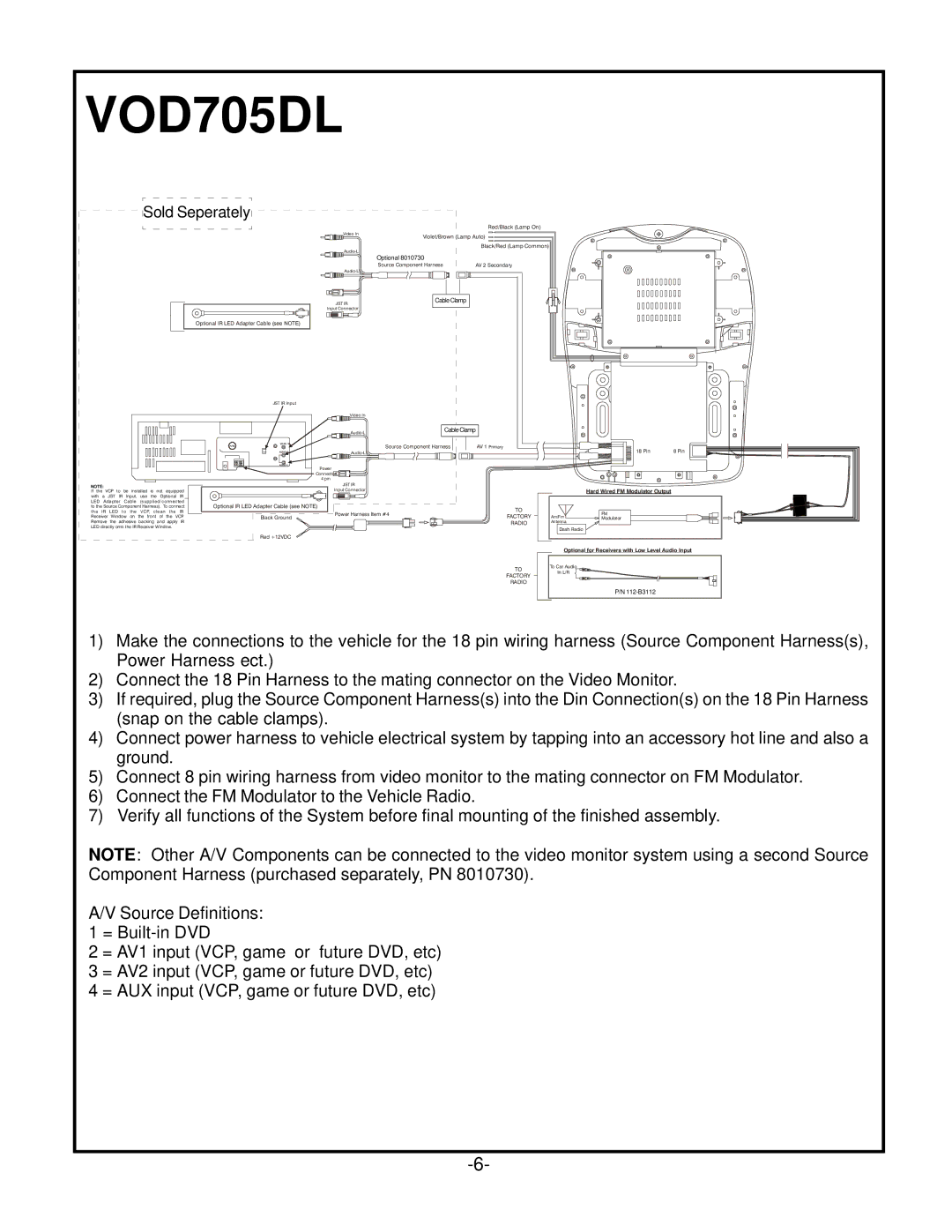
1)Make the connections to the vehicle for the 18 pin wiring harness (Source Component Harness(s), Power Harness ect.)
2)Connect the 18 Pin Harness to the mating connector on the Video Monitor.
3)If required, plug the Source Component Harness(s) into the Din Connection(s) on the 18 Pin Harness (snap on the cable clamps).
4)Connect power harness to vehicle electrical system by tapping into an accessory hot line and also a ground.
5)Connect 8 pin wiring harness from video monitor to the mating connector on FM Modulator.
6)Connect the FM Modulator to the Vehicle Radio.
7)Verify all functions of the System before final mounting of the finished assembly.
NOTE: Other A/V Components can be connected to the video monitor system using a second Source Component Harness (purchased separately, PN 8010730).
A/V Source Definitions:
1=
2= AV1 input (VCP, game or future DVD, etc)
3= AV2 input (VCP, game or future DVD, etc)
4= AUX input (VCP, game or future DVD, etc)