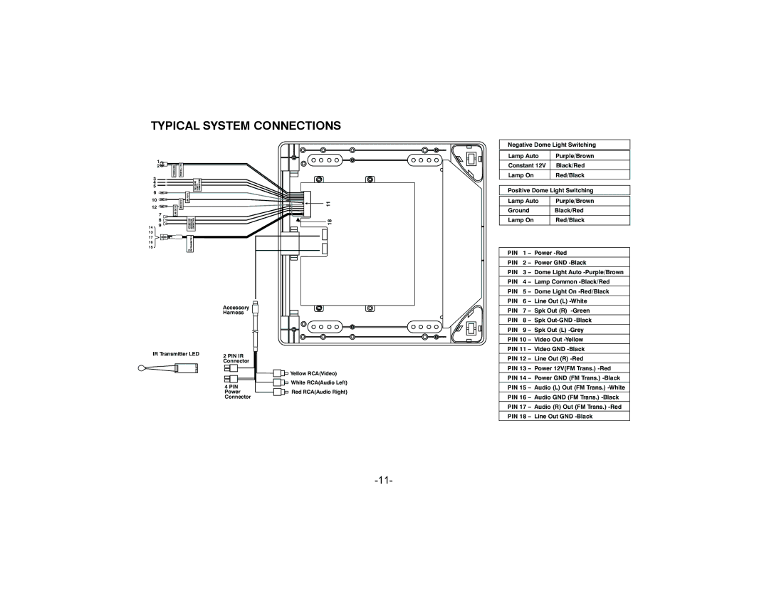
TYPICAL SYSTEM CONNECTIONS
Negative Dome Light Switching
1
2![]()
3
4
5
6
10
12
7
8
149
17
16
15
POWER(GND)
LINE
![]() LINE
LINE ![]()
CONNECTION
LIGHT’S
TWO DOME
| OUTL- |
|
|
| LINE |
|
|
|
|
|
|
| SPEAKER OR | HEADPHONE CONNECTION | |
|
|
|
|
|
|
|
|
| TO | FM TRANSMITTER |
|
18 11
Lamp Auto | Purple/Brown |
Constant 12V | Black/Red |
Lamp On | Red/Black |
| |
Positive Dome Light Switching | |
|
|
Lamp Auto | Purple/Brown |
|
|
Ground | Black/Red |
|
|
Lamp On | Red/Black |
|
|
PIN | 1 | – Power |
PIN | 2 | – Power GND |
PIN | 3 | – Dome Light Auto |
PIN | 4 | – Lamp Common |
PIN | 5 | – Dome Light On |
PIN | 6 | – Line Out (L) |
Accessory
Harness
IR Transmitter LED | 2 PIN IR | ||
| |||
| Connector | ||
|
|
|
|
|
|
|
|
|
|
|
|
| 4 PIN | ||
| Power | ||
| Connector | ||
![]() Yellow RCA(Video)
Yellow RCA(Video) ![]()
![]() White RCA(Audio Left)
White RCA(Audio Left)
Red RCA(Audio Right)
PIN | 7 – | Spk Out (R) | |
PIN | 8 | – | Spk |
PIN | 9 | – | Spk Out (L) |
PIN 10 | – | Video Out | |
PIN 11 | – | Video GND | |
PIN 12 – Line Out (R)
PIN 13 – Power 12V(FM Trans.)
PIN 14 – Power GND (FM Trans.)
PIN 15 – Audio (L) Out (FM Trans.)
PIN 16 – Audio GND (FM Trans.)
PIN 17 – Audio (R) Out (FM Trans.)
PIN 18 – Line Out GND