Manuals
/
Avaya
/
Computer Equipment
/
Switch
Avaya
P112T
manual
Connect the fiber-optic cables to the front panel ports
Models:
P112T
1
9
12
12
Download
12 pages
23.33 Kb
5
6
7
8
9
10
11
12
Install
Diagnostics
Safety Precautions
Page 9
Image 9
Page 8
Page 10
Page 9
Image 9
Page 8
Page 10
Contents
24-PORT STACKABLE ETHERNET WORKGROUP SWITCH
Avaya
Installation Guide
P112T
Page
PRECAUTIONS DE SECURITÉ
SAFETY PRECAUTIONS
Important Information
Preface
4. Austauschen einer durchgebrannten Sicherung NUR mit der gleichen Sorte und Belastbarkeit wie sie auf der Sicherheitsaufschrift markiert ist. Die Aufschrift befindet sich neben der Stromzufuhr wo sich auch der Sicherungskasten befindet
Overview
Chapter
Description
Overview
Chapter
Installation
Standalone Operation
Stacking Operation
The Port Mode Half/Full Duplex parameter, will be set to Half Duplex
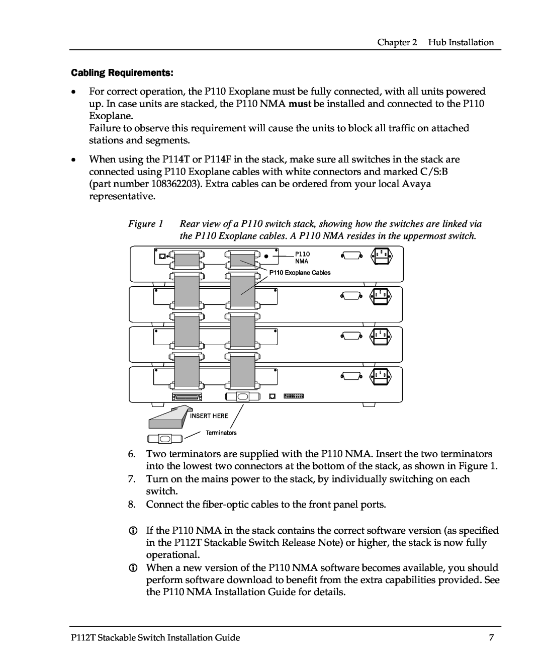
8. Connect the fiber-optic cables to the front panel ports
Rack Mounting
Diagnostics
Function LEDs
Port LEDs
2003 Avaya Inc. All rights reserved
Document number 130001 Rev. A
Top
Page
Image
Contents