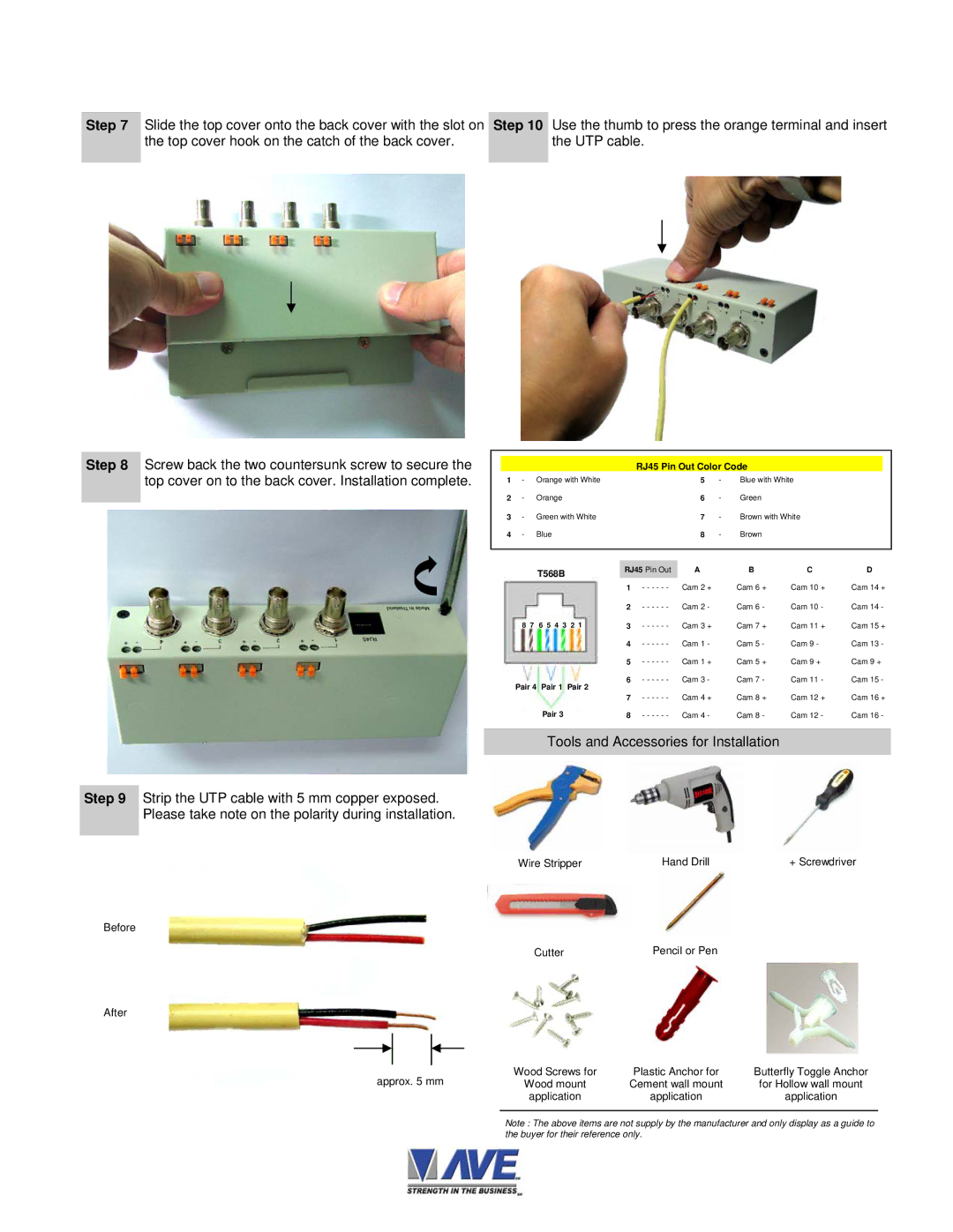
Step 7 | Slide the top cover onto the back cover with the slot on | Step 10 | Use the thumb to press the orange terminal and insert |
| the top cover hook on the catch of the back cover. |
| the UTP cable. |
|
|
|
|
Step 8 Screw back the two countersunk screw to secure the top cover on to the back cover. Installation complete.
Step 9 Strip the UTP cable with 5 mm copper exposed. Please take note on the polarity during installation.
Before
After
approx. 5 mm
RJ45 Pin Out Color Code
1 | - | Orange with White |
| 5 | - | Blue with White |
| |
2 | - | Orange |
| 6 | - | Green |
|
|
3 | - | Green with White |
| 7 | - | Brown with White |
| |
4 | - | Blue |
| 8 | - | Brown |
|
|
|
|
|
|
|
|
|
|
|
|
| T568B | RJ45 Pin Out | A |
| B | C | D |
|
|
| 1 - - - - - - | Cam 2 | + | Cam 6 + | Cam 10 + | Cam 14 + |
|
|
| 2 - - - - - - | Cam 2 | - | Cam 6 - | Cam 10 - | Cam 14 - |
| 8 7 | 6 5 4 3 2 1 | 3 - - - - - - | Cam 3 | + | Cam 7 + | Cam 11 + | Cam 15 + |
|
|
| 4 - - - - - - | Cam 1 | - | Cam 5 - | Cam 9 - | Cam 13 - |
|
|
| 5 - - - - - - | Cam 1 | + | Cam 5 + | Cam 9 + | Cam 9 + |
| Pair 4 | Pair 1 Pair 2 | 6 - - - - - - | Cam 3 | - | Cam 7 - | Cam 11 - | Cam 15 - |
|
| Cam 4 | + | Cam 8 + | Cam 12 + | Cam 16 + | ||
|
|
| 7 - - - - - - | |||||
|
| Pair 3 | 8 - - - - - - | Cam 4 | - | Cam 8 - | Cam 12 - | Cam 16 - |
Tools and Accessories for Installation
Wire Stripper | Hand Drill | + Screwdriver |
Cutter | Pencil or Pen |
Wood Screws for | Plastic Anchor for | Butterfly Toggle Anchor |
Wood mount | Cement wall mount | for Hollow wall mount |
application | application | application |
Note : The above items are not supply by the manufacturer and only display as a guide to the buyer for their reference only.
