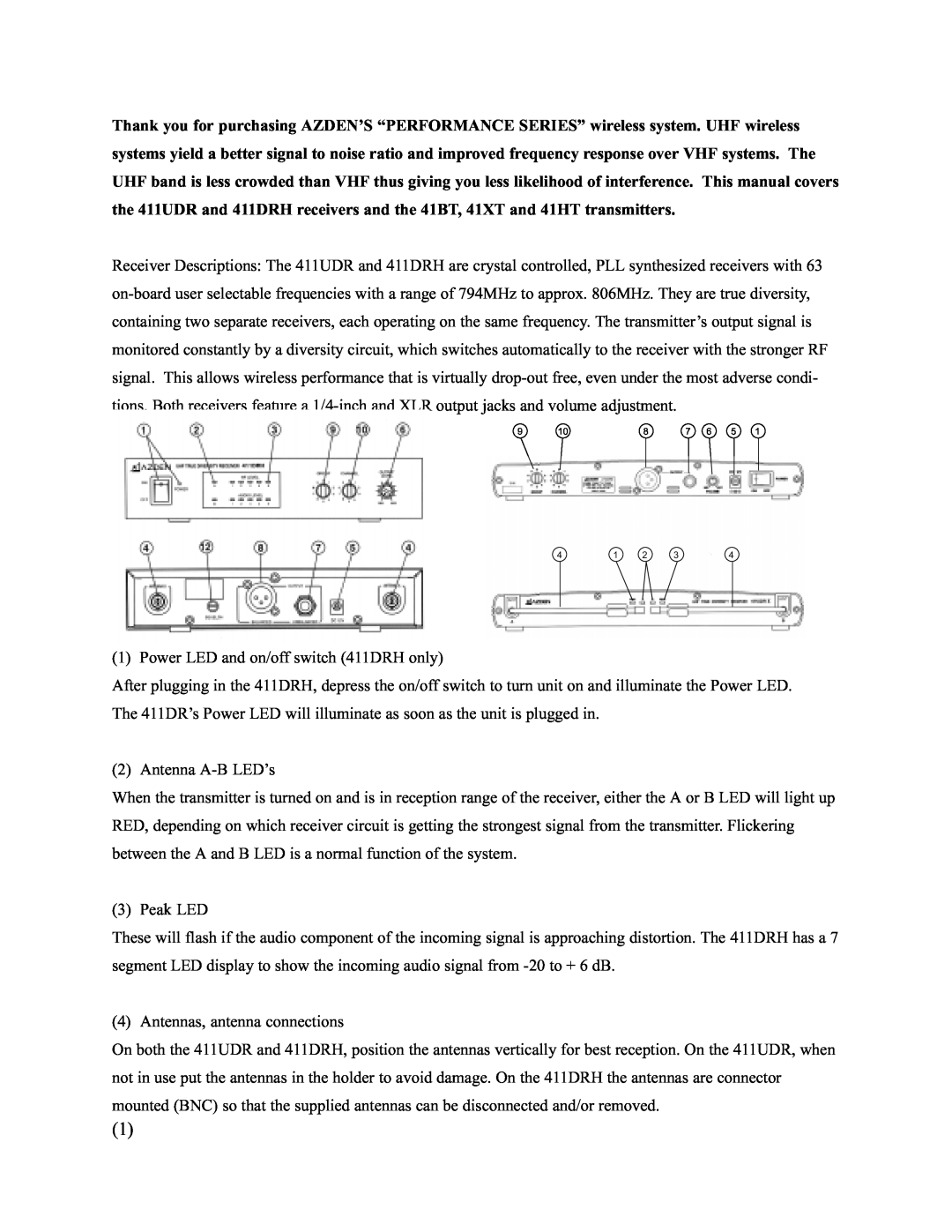
411UDR specifications
Azden is a renowned brand in the world of audio equipment, particularly notable for its advanced wireless microphone systems. Among their offerings, the Azden 51XT, 411UDR, 511DRH, 51HT, and 51BT are prominent models, each designed with unique features and capabilities to cater to various audio production needs.The Azden 51XT is a compact wireless microphone system that is especially favored for its versatility. It operates in the UHF band, providing a reliable transmission with minimal interference. Its lightweight design makes it ideal for portable applications, while the built-in low-cut filter helps reduce wind noise and unwanted low-frequency sounds, enhancing audio clarity.
The 411UDR model stands out with its robust features, including dual-channel operation, which allows users to connect two microphones simultaneously. This is particularly useful in interviews or panel discussions, where multiple voices need to be captured. Its advanced frequency selection capability helps users avoid crowded channels, ensuring a clear and uninterrupted signal.
Moving to the 511DRH, this wireless system is characterized by its digital transmission technology, offering superior sound quality and extended range. With a quick setup process, users can easily switch between various frequencies, making it suitable for dynamic environments. The 511DRH also features a durable build, with water-resistant components that ensure reliability in various weather conditions.
The 51HT handheld microphone from Azden is designed for vocal clarity and ease of use. It includes an integrated transmitter that simplifies setup, eliminating the need for additional cables. The microphone's frequency response is finely tuned to capture speech, making it an excellent choice for live performances and presentations.
Finally, the 51BT model is particularly unique, as it combines wireless transmission with Bluetooth technology. This feature allows for seamless connectivity with smartphones and other Bluetooth-enabled devices, enabling users to record or stream audio directly. The 51BT is especially popular among content creators and vloggers, thanks to its user-friendly design and high-quality sound performance.
In summary, the Azden 51XT, 411UDR, 511DRH, 51HT, and 51BT wireless microphone systems offer a range of innovative technologies and features tailored for diverse audio applications. Whether for professional use, content creation, or live events, these models deliver exceptional performance and reliability, making Azden a trusted name in the audio industry.
